Examining the installation site, Installing the switch, Attaching the slide rails to the rack – H3C Technologies H3C S7500E Series Switches User Manual
Page 8
5
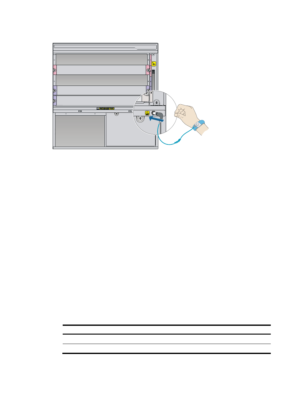
Figure 3 Attaching an ESD wrist strap
Examining the installation site
The switch can only be used indoors. To make sure the switch operates correctly and prolong its service
lifetime, the installation site must meet the requirements for load-bearing, temperature, humidity,
cleanness, EMI, grounding power module, ventilation, and space. For more information, see H3C
S7500E Switch Series Installation Guide.
If you are to install the switch in an enclosed rack, make sure the rack meets the following requirements:
•
For all S7500E models, a minimum of 100 mm (3.94 in) of clearance between the front rack posts
and the front door for accommodating the cable management brackets.
•
For the S7502E, a minimum of 440 mm (17.32 in) of clearance between the front rack posts and the
rear door for accommodating the chassis and power cord deployment.
Installing the switch
Attaching the slide rails to the rack
1.
Read the signs on the slide rails to identify the left and right slide rails and their front ends, as
.
Table 4 Description for signs on the slide rails
Sign
Meaning
Remarks
F/L
Front end of the left slide rail
Mount this end to the front left rack post.
F/R
Front end of the right slide rail
Mount this end to the front right rack post.
2.
Mark the installation position on the rack for the slide rails: