Jordan Valve Mark 50 Series – Self-Operated Back Pressure Regulator User Manual
Installation, Start-up procedure, Maintenance
3170 Wasson Road • Cincinnati, OH 45209 USA
Phone 513-533-5600 • Fax 513-871-0105
[email protected] • www.jordanvalve.com
I & M Mark 501 / 502
Installation & Maintenance Instructions for
Mark 501/502 High Flow Back Pressure Regulators
Warning: Jordan Valve Back Pressure Regulators must only be used, installed and repaired in accordance with these
Installation & Maintenance Instructions. Observe all applicable public and company codes and regulations. In the event
of leakage or other malfunction, call a qualified service person; continued operation may cause system failure or a
general hazard. Before servicing any valve, disconnect, shut off, or bypass all pressurized fluid. Before disassembling a
valve, be sure to release all spring tension.
Please read these instructions carefully!
Your Jordan Valve product will provide you with long, trou-
ble- free service if it is correctly installed and maintained.
Spending a few minutes now reading these instructions
can save hours of trouble and downtime later. When mak-
ing repairs, use only genuine Jordan Valve parts, available
for immediate shipment from the factory.
Installation
To protect the regulator from grit, scale, thread chips,
1.
and other foreign matter, all pipe lines and piping
components should be blown out and thoroughly
cleaned before the regulator is installed.
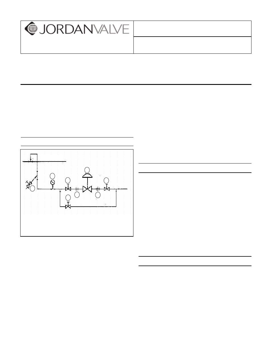
Shutoff valves, pressure gauges, and bypass piping
2.
should be installed as indicated in the diagram to
provide easier adjustment, operation, and testing.
In preparing threaded pipe connections, care should
3.
be exercised to prevent pipe sealing compound
from getting into the pipe lines. Pipe sealing com-
pound should be used sparingly, leaving the two
end threads clean. Jordan uses, and recommends,
thread sealer Teflon ribbon.
A line strainer should be installed on the inlet side of
4.
the regulator to protect it from grit, scale and other
foreign matter. A 0.033 perforated screen is usually
suitable. Line strainers are available from Jordan
Valve.
Install the regulator in the highest horizontal line of
5.
piping to provide drainage for inlet and outlet pip-
ing, to prevent water hammer, and to obtain faster
regulation.
The flow arrow on the regulator body must be point-
6.
ed in the direction of flow. The regulator may be in-
stalled vertically or horizontally without affecting its
operation.
For best control, 3’ 0” straight sections of pipe should
7.
be installed on either side of the regulator.
In hot vapor lines, upstream piping near the regula-
8.
tor should be insulated to minimize condensation.
Start-Up Procedure
With the inlet and outlet shutoff valves closed:
Throttle the bypass valve so that the pressure to be
1.
controlled is maintained near the set point.
Slowly open the inlet shutoff valve.
2.
Open the outlet shutoff valve.
3.
Slowly close the bypass valve, but do not close it
4.
fully until you are certain that the regulator has con-
trol of the system.
To change the controlled pressure, turn the adjust-
5.
ing screw clockwise to increase pressure, counter-
clockwise to decrease pressure.
Body & end cap should be retightened per torque
6.
procedures after valve reaches operating temp.
Maintenance
Caution: Make certain that there is no pressure in the
valve before loosening any fittings or joints. The follow-
ing steps are recommended:
Close inlet shutoff valve.
1.
Allow pressure to bleed off through downstream
2.
piping. Do not cause a reverse flow through valve
by bleeding pressure from upstream side of valve.
When downstream pressure gauge indicates no
3.
pressure in the line, close the outlet shutoff valve.
Bypass
Main Line
5
2
1
2
1
1
4
3
1. Shutoff Valve
2. Pipe Union
3. Strainer & Drain Valve
4. Pressure Gauge
5. Back Pressure Regulator