Jordan Valve Mark 25 Series – Tempilot Temperature User Manual
I & m mark 25, Operation, Sensitivity
3170 Wasson Road • Cincinnati, OH 45209 USA
Phone 513-533-5600 • Fax 513-871-0105
[email protected] • www.jordanvalve.com
I & M Mark 25
Installation & Maintenance Instructions for
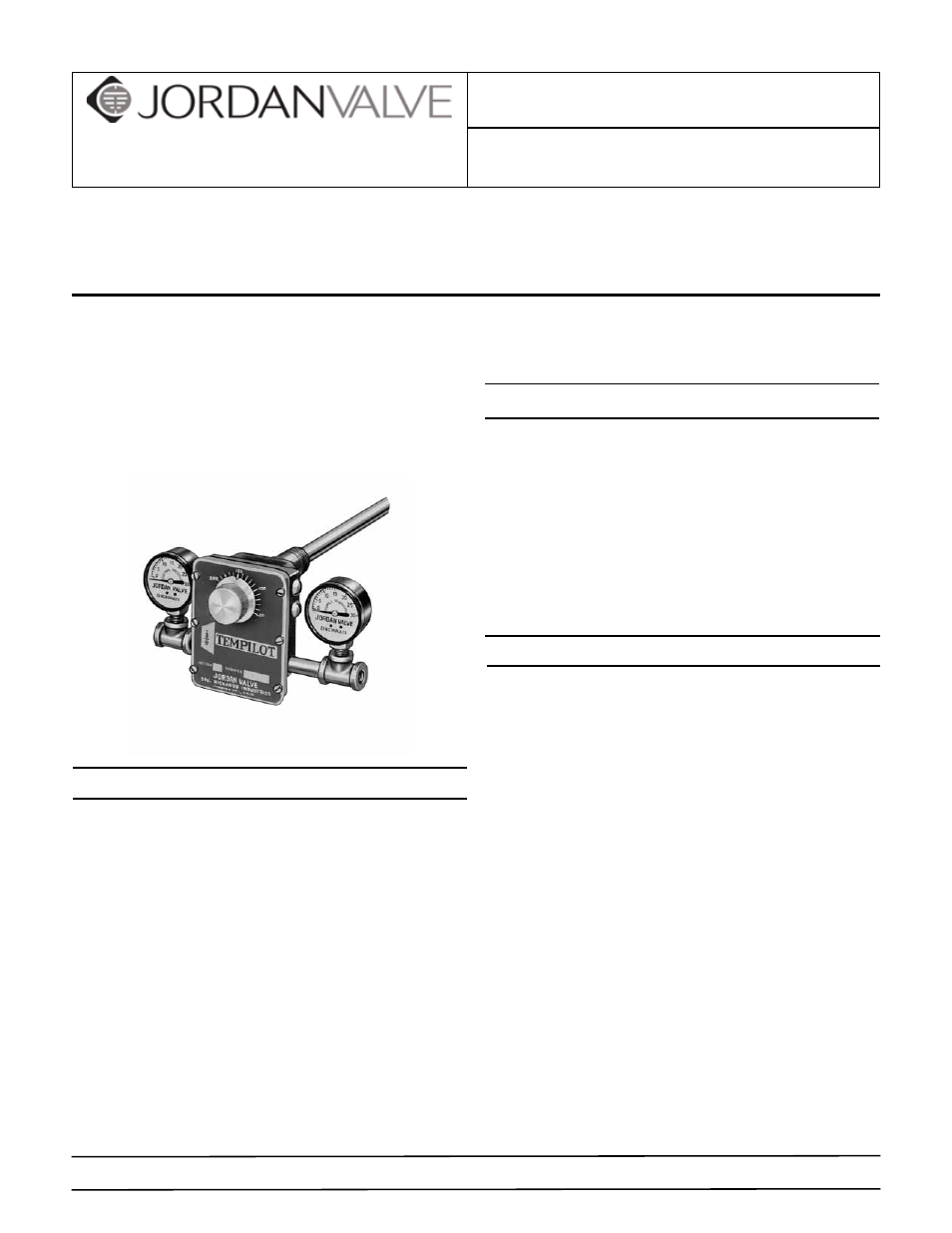
Mark 25 Tempilot
TM
Temperature Controller
Warning: Jordan Valve Temperature Controllers must only be used, installed and repaired in accordance with these
Installation & Maintenance Instructions. Observe all applicable public and company codes and regulations. In the event
of leakage or other malfunction, call a qualified service person; continued operation may cause system failure or a
general hazard. Before servicing any valve, disconnect, shut off, or bypass all pressurized fluid. Before disassembling a
valve, be sure to release all spring tension.
Please read these instructions carefully!
Your Jordan Valve product will provide you with long, trou-
ble-free service if it is correctly installed and maintained.
Spending a few minutes now reading these instructions
can save hours of trouble and downtime later. When mak-
ing repairs, use only genuine Jordan Valve parts, available
for immediate shipment from the factory.
Operation
A temperature change in the medium being controlled
creates a change in length of the sensitive tube (1). An
increase in temperature lengthens the sensitive tube (1)
and moves the Invar rod (2) away from the lever (3). The
lever (4), which pivots at Point A, is moved to close the
exhaust valve (4) by spring (5). This permits the supply (air
or water) (S) to increase the pressure in the control line
(R) and close the normally open valve. A decrease in tem-
perature shortens the sensitive tube (1) and moves the
Invar rod against the lever (3). The lever (3) moves against
the pressure spring (5), to open the exhaust valve (4). This
exhausts the pressure in the control line and opens the
valve.
The sensitivity adjustment screw (6) regulates the rate
of flow of the supply air (or water) to the controller to a
change in temperature. Turning the screw clockwise in-
creases the sensitivity by reducing the flow and increas-
ing the response time. Turning the screw counterclock-
wise decreases the sensitivity by increasing the flow and
reducing the response time.
Sensitivity
The sensitivity of the Tempilot controller is adjusted by
turning the restriction screw. (The restriction screw is
factory set for air operation.) For water operation, the re-
striction screw should be opened a minimum of 1/2 turn
and recalibrated. Restriction screw must NEVER be fully
closed. Make adjustments slowly, allowing about two min-
utes after each adjustment for the controller to balance.
NOTE: If sensitivity is changed, controller must be reca-
librated.
Installation
The Jordan Tempilot requires a clean, reliable supply of
compressed air or cold water at 15 - 25 pounds pressure.
Other fluids may be used, such as gas, oil, etc., providing
provision is made for safe disposal.
AIR OPERATION — The Tempilot should normally be in-
stalled in the horizontal position; however, other positions
may be used if the supply and control connections are
parallel with the ground and calibration is checked after
installation.
WATER OPERATION — The Tempilot must be installed in
the horizontal position with the drain connection at the
bottom. Drain piping should be 3/8” minimum for posi-
tive draining at all times.
1.
Select the sensitive element location with care to as-
sure satisfactory results. Bulb must project entirely
into the water or air being controlled.
2.
Flush or blow out all lines before making final con-
nections. Put supply pressure through all control
lines and check for leaks.
3.
Always locate the Tempilot as close to the control
valve as possible. Piping between the Tempilot and
the control valve should be 1/8” brass pipe or 1/4”
PROTECT VALVES WITH LINE STRAINERS