Jordan Valve 657M Series Diaphragm Actuator User Manual
I & m 657m series
I
nstallatIon
The 657M Diaphragm Actuator is usually delivered
furnished mounted on a Jordan valve body. When
installing the valve body into the pipeline, consult the
instructions for that particular valve body. Should you
have any questions during the installation procedure,
consult your Jordan Valve representative.
The loading pressure is connected to the NPT connec-
tion in the top of the diaphragm case (1/4” for sizes 30
through 60, 1/2” size 70). With larger sizes, it may be
beneficial to reduce the connection down to 1/4”. Pipe
or tubing may be used, and should be run to the out-
put pressure connection on the automatic controller.
Avoid transmission lag in the control signal by keeping
the length of pipe or tubing as short as possible. When
long distances are involved, install a valve positioner
on the actuator. If the valve positioner is provided as
part of the original equipment, the loading pressure
connection will be made at the Jordan Valve manufac-
turing facility.
If the 657M Diaphragm Actuator is shipped alone for
field mounting, it should be mounted onto the valve
body and secured in place with the yoke locknut.
Clamp the actuator stem and valve plug stem together
using the stem connector to provide the proper valve
travel. Refer to the “Assembly Instructions” section of
this manual for complete instructions.
For ease of service, ensure that the control valve is
located for easy access and serviceability with room
above for accessibility. Ensure that sufficient room is
provided below should removal of the actuator and
valve plug be necessary.
o
peratIon
and
a
djustment
Refer to the nameplate on the yoke of the actuator
for details on the specific construction and operating
range. The requirements of your specific application
will dictate the spring and diaphragm used in your
657M Actuator. When in service, the actuator will create
full travel of the valve plug when diaphragm pressure is
applied according to the range indicated on the name
plate. Generally, the diaphragm pressure range is 3 to
15 PSI or 6 to 30 PSI, but other ranges may be used.
Pressure within the valve body creates forces on the
valve plug which directly affect the actual operating
diaphragm pressure range. When pressure conditions
in the valve body are different from those indicated in
the factory settings, the valve may not stroke completely
over the indicated range. To achieve correct travel for
the diaphragm pressure range utilized, a simple spring
adjustment is necessary. Note, however, that the actua-
tor spring has a fixed pressure span and that adjust-
ment of the spring compression simply shifts this span
up or down to make the travel of the valve correspond
with the diaphragm pressure range.
I
ntroductIon
All Jordan Valve equipment, including actuators, are
to be installed and maintained in accordance with
instructions supplied by Jordan Valve. Only qualified
personnel may install and service the actuator, and, if
necessary, contact a gas service person.
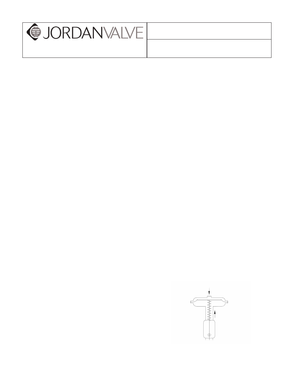
Figure 1: Schematic of 657M Actuator
3170 Wasson Road • Cincinnati, OH 45209
Phone 513.533.5600 • Fax 513.871.0105 (f)
[email protected] • www.jordanvalve.com
I & M 657M Series
Installation & Maintenance Instructions for the
657M Series Diaphragm Actuator
657M Direct Acting Diaphragm Actuator
Warning: Jordan Valve Control Valves must only be used, installed and repaired in accordance with these Installa-
tion & Maintenance Instructions. Observe all applicable public and company codes and regulations. In the event
of leakage or other malfunction, call a qualified service person; continued operation may cause system failure or
a general hazard. Before servicing any valve, disconnect, shut off, or bypass all pressurized fluid. Before disassem-
bling a valve, be sure to release all spring tension.
Air Pushes Down
Spring Lifts
Stem moves upward with loss of
operating medium