Larco 433 MHz Receiver & Transmitter User Manual
System, Installation
www.larco.com
433 MHz Receiver & Transmitter
Installation Instructions
2
1
System
The Larco ultra-small receiver and transmitters operate at 433.92 MHz (acceptable
in the United States, Canada and any European Union member state) and employ
code-hopping technology to reduce false activations. The receiver only operates
after learning a transmitter’s signal through the simple procedure outlined on the
next page. This programming procedure eliminates the need to set dip switches and
involves a simple press of the programming button located on the top cover of the
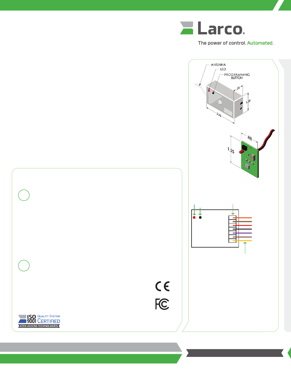
receiver (see
Diagram 1
).
NOTE: Read this document in its entirety before installing any Larco transmitter or
receiver. It is important to complete the programming procedure before installing
the receiver in its final location. The installer must have access to the receiver’s
programming button and must be able to view the receiver’s LED (Light Emitting
Diode) during the programming process.
Mount the receiver in a location so that the antenna is not surrounded
by metal. Metal attenuates RF signals causing a reduction in range and
inconsistency of signal reception. Door operator motors and controls may
also cause radio frequency interference.
Locate the receiver away from the door control’s motor and power
supply. If the receiver is mounted in a metal enclosure, drill a hole in the
enclosure and thread as much of the antenna as possible through the hole.
This reduces the effects the metal enclosure will have on the receiver’s
reception.
The receiver comes equipped with a wiring harness for easy installation.
Reference the wiring diagram (see
Diagram 2
) for proper connections.
Installation
Complete the programming procedure before placing the receiver in final location.
The receiver and transmitter comply with FCC part 15/15.231, Industry Canada RSS-210,
EN55022A, EN55024, EN300-220-3, and EN301-489-1. Operation is subject to the following
two conditions: (1) This device may not cause harmful interference, and (2) this device must
accept any inerference received, including interference that may cause undesired operation.
This product may be susceptible to local transmissions being generated near the transmitter’s
fundamental frequency. Testing has shown some susceptibility in a frequency range of
416-440 MHz.
Diagram 1: Receiver and Transmitter Dimensions
Diagram 2: Receiver Wiring Harness
Orange: Relay Output – Normally Open
Brown with White Stripe: Relay Output – Common
Red: 24VAC/24VDC Power
Black: Ground
Purple : 12VAC/12VDC Power
Brown: Relay Output – Common
Yellow: Relay Output – Normally Closed
Output N.O.
Output Common
24VAC/24VDC
GND
12VAC/12VDC Power
Output Common
Output N.C.
Orange
Brown/White Stripe
Red
Black
Purple
Brown
Yellow
Approx.
6 in. / 152 mm
Receiver Terminals
LED
RECEIVER
Button
Transmitter –
Item # 234475
Receiver –
Item # 233804