Setting the transmitter address, Otx-***-hh-lr8-ms button assignments, Contention considerations – Linx Technologies OTX-xxx-HH-LR8-MS User Manual
Page 5: Battery replacement, Assembly diagram
– –
– –
4
5
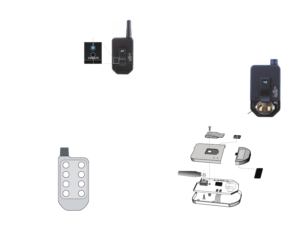
Setting the Transmitter Address
The MS Long-Range Handheld
Transmitter allows the selection
of one of 16,777,216 (2
24
) unique
addresses. All transmitters are
supplied set to a unique address
to avoid contention with other
units; however, the address can be
changed. This is accomplished by
using a paper clip or probe to press
the CREATE button on the board
through the hole in the back of the
case. Press the button and an LED
lights up in the MODE_IND window,
indicating that the address is being
created. The address is randomized for as long as the button is held down.
Release the button and the randomized address is saved and the LED
begins flashing to indicate that the Control Permissions may now be set.
Press the buttons that the transmitter should have the authority to access.
Press the CREATE button with the paper clip again or wait 17 seconds
for it to time out. The address and Control Permissions are now set. The
decoder needs to learn the address before it will accept any transmissions.
Please see the Typical Applications section of this data guide or the MS
Series Decoder Data Guide for details.
OTX-***-HH-LR8-MS Button Assignments
Figure 6 illustrates the relationship between the button locations and
encoder data lines.
Contention Considerations
It is important to understand that only one transmitter at a time can be
activated within a reception area. While the transmitted signal consists
of encoded digital data, only one carrier of any particular frequency can
occupy airspace without contention at any given time. If two transmitters
are activated in the same area at the same time, then the signals will
interfere with each other and the decoder will not see a valid transmission,
so it will not take any action.
Battery Replacement
The remote unit utilizes a standard CR2032 lithium
button cell. In normal use, it provides 1 to 2 years of
operation. To replace the battery, remove the access
cover by pressing firmly on the label area and sliding it
off. Once the unit is open, remove the battery by sliding
it from beneath the holder. Replace it with the same
type of battery while observing the polarity shown in
Figure 7.
There may be the risk of explosion if the battery is
replaced by the wrong type.
Assembly Diagram
Battery access
MODE_IND Window
CREATE Button
D6
D7
D4
D5
D2
D3
D0
D1
FCC ID: OJM-OTX-XXX-LRMSA
IC: 5840A-LRMSXXXA
418MHz
Figure 5: CREATE Button Access
Figure 6: OTX-***-HH-LR8-MS Button Assignments
Figure 7: Battery Access
Figure 8: OTX-***-HH-LR8-MS Assembly
+