Kichler 10581 User Manual
Kichler Hardware
1)
Turn off power.
2)
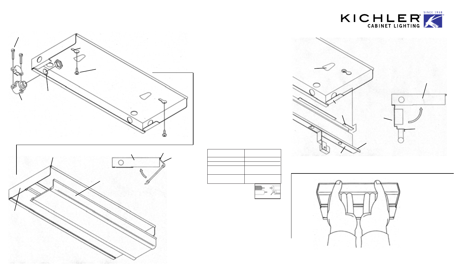
Hold fixture housing in desired mounting position and mark position of
keyholes. Put fixture housing down and start screw at marks.
3)
Remove the knockout which allows for the easiest access to conduit.
4)
Assemble conduit connector to knocked-out hole on fixture housing.
(Reference illus. for conduit connector assembly.)
5)
Run wire through assembled conduit connector.
The provided conduit fitting may only be used with the following:
A)
14/2 to 10/2 steel armored cable.
B)
3/8 in. trade sized reduced wall flexible steel or aluminum conduit; or
C)
14/2 to 10/2 non-metallic sheathed cable
6)
Slip large portion of keyhole over screwheads and push fixture to one
side. This will allow both hands freedom for tightening screws.
7)
Tighten screws on conduit connector to clamp conduit in position.
8)
Slip feet at back of wiring cover over ledge at each
end of fixture housing and let wiring cover hang
freely.
9)
Wrap ground wire from supply around ground
screw and thread on green hexnut. Hexnut should
trap wire inside of dimples.
• Electrical shock, overheating, low or no light output
and shortened lamp life can result if proper
grounding is not done.
• To accomplish proper grounding there must be a
wire or bare metal contact between this fixture
and either a grounded incoming wire or grounded
metal base.,
• When non-metallic conduit systems are used
the ground wire from the fixture must terminate
at the ground of the power supply panel.
10) Make wire connections (connectors provided.)
11) Swing wiring cover up towards fixture housing.
With fingers placed on rear of fixture housing
and thumbs on wiring cover face, swing wiring
cover up towards fixture housing.
At tabs apply pressure to wiring cover face with
thumbs until lip slips under tabs,
12) Insert recommended bulbs, if removed.
13) Plastic face of diffuser has a slight lip. Insert lip into channel at front
of fixture housing.
14) Swing diffuser up towards fixture housing until diffuser snaps into
place.
15) To remove diffuser: Place thumbs on diffuser face and finger tips on lip
between diffuser face and diffuser glass. Apply slight pressure to diffuser
face with thumbs and pull fingers toward thumbs.
FIXTURE HOUSING
CHANNEL
PLASTIC
FACE
(THIS END
FIRST)
PLASTIC FACE
CHANNEL
FIXTURE
HOUSING
IS-10580-US
KEY
HOLE
SCREW
FIXTURE
HOUSING
KNOCKOUT
CONDUIT
CONNECTOR
SCREW
FIXTURE
HOUSING
TAB
LEDGE
WIRING
COVER
FOOT
LIP
WIRING COVER
FACE
FIXTURE
HOUSING
WIRING
COVER
LIP
Connect Black or
Red Supply Wire to:
Connect
White Supply Wire to:
Black
White
*Parallel cord (round & smooth)
*Parallel cord (square & ridged)
Clear, Brown, Gold or Black
without tracer
Clear, Brown, Gold or Black
with tracer
Insulated wire (other than green)
with copper conductor
Insulated wire (other than green)
with silver conductor
*Note: When parallel wires (SPT I & SPT II)
are used. The neutral wire is square shaped
or ridged and the other wire will be round in
shape or smooth (see illus.)
Neutral Wire
Date Issued: 6/3/03