Marwin Valve UT Series Pneumatic Actuators User Manual
I & m ut series (2003 design), Scope, Main characteristics
3170 Wasson Road • Cincinnati, OH 45209 USA
Phone 513-533-5600 • Fax 513-871-0105
[email protected] • www.marwinvalve.com
I & M UT Series (2003 Design)
Installation & Maintenance Instructions for
Marwin UT Series Actuators
UT-0 thru UT-4.5 (2003 Design)
Warning: Marwin Valve Ball Valves must only be used, installed and repaired in accordance with these Installation &
Maintenance Instructions. Observe all applicable public and company codes and regulations. In the event of leakage
or other malfunction, call a qualified service person; continued operation may cause system failure or a general hazard.
Please read these instructions carefully!
Your Marwin Valve product will provide you with long, trouble-free service if it is correctly installed and maintained.
Spending a few minutes now reading these instructions can save hours of trouble and downtime later. When making
repairs, use only genuine Marwin Valve parts, available for immediate shipment from the factory.
Scope
This manual is intended as a guide to assist customers in the storage, installation, and maintenance of Marwin UT Se-
ries Pneumatic Actuators UT-0 thru UT-4.5 ~ 2003 Design. See photo on back page for further identification.
Main Characteristics
Maximum Air Supply: 116 psi (8 bar)
Supply: Dry air (STANDARD). Other fluids or gases are possible if compatible with actuator materials.
Temperature: From -4°F to +185°F (-20°C to +85°C) for standard version with NBR seals.
From -4°F to +302°F (-20°C to +150°C)) for HIGH TEMP version (Viton seals).
From -40°F to +185°F (-40°C to +85°C) for LOW TEMP version.
Rotation: 90° stroke with regulation +/-5° for open and closed position (double adjustment). Upon request full
stroke regulation 0° / 90°.
Lubrication: during assembly, for the actuator life.
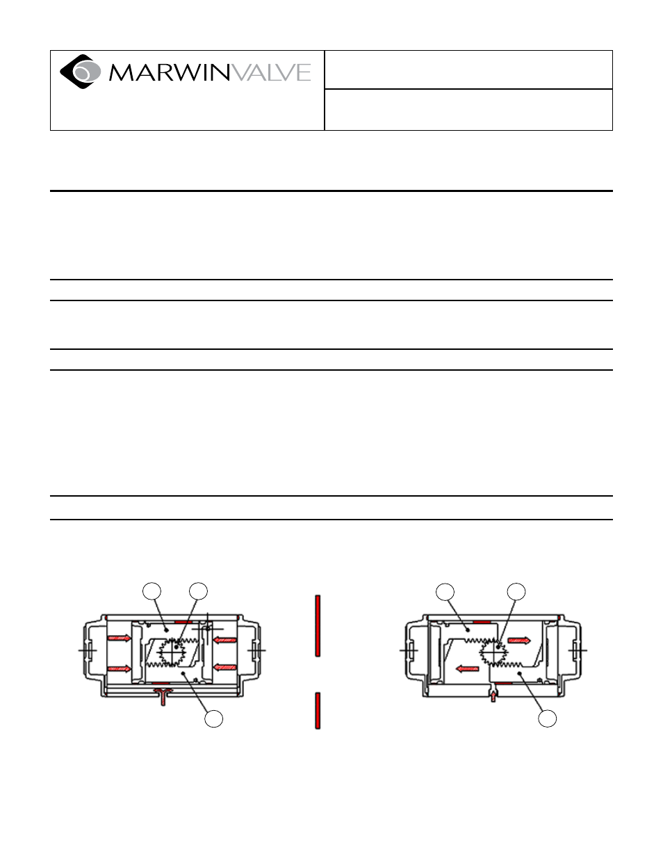
Operating Principle
The Marwin UT pneumatic actuator is a quarter-turn rack and pinion type that transforms the linear motion of the pis-
tons (11), due to the thrust caused by the pressure on the surface area, to a 90° rotary motion of the pinion (2).
Pressurizing the left or bottom air port (P1) fills the exter-
nal chambers. The action of the pressure on the surface
of the pistons (11) creates a force (F) that pushes them
toward the pinion, generating a torque with CLOCKWISE
ROTATION.
Pressurizing the right or top air port (P2) fills the internal
chamber. The action of the pressure on the surface of
the pistons (11) creates a force (F1) that pushes them
toward the end caps, generating a torque with COUN-
TERCLOCKWISE ROTATION.
Double Acting
CLOSED
OPEN
IN
AIR
P1
IN
AIR
P2
11
2
2
11
11
11
F
F
F1
F1