RISCO Group WL 72P User Manual
Wireless pulse count transmitter, Wl 72p, C risco
E N G L I S H
Step 4: Selection of Installation Location
a. Select a location best suited for communication quality and near the
intended wired detector (for switched sensor). Place the unit at the highest
possible position.
b. Temporarily attach the unit to this point using two sided adhesive tape.
c. Generate an Alarm signal (by momentarily opening or closing the input
terminals) and verify that the receiver has received the signal. If the alarm
signal is not detected, reposition the transmitter and try again.
Step 5: Final Mounting
Separate the back part of the transmitter (fig. 3), and mount all the parts in
place (fig. 4).
If relevant, connect the sensor to the input terminals.
SPECIFICATIONS
1. GENERAL DESCRIPTION
The WL 72P is dual function supervised transmitter that can be
connected to external contacts (universal protection) or special contacts
with a wire for shutter protection.
It operates together with RISCO Group receivers and is powered by
a standard 3-volt lithium battery.
TRANSMITTER MAIN FEATURES:
•
Operates up to 1000ft (300m) range (outdoors)
RF high/low power
Uses one of more than 16 million pseudo-randomly selected preset
coded addresses for setup
Microprocessor design
Extended battery life
Fully supervised
Selective function (universal or shutter protection)
Selective pulse counter (for shutter control function)
Selective response time and input (NO/NC) for universal control function
Back and cover tamper protection
•
•
•
•
•
•
•
•
•
2. OPTIONAL FUNCTION MODES
The transmitter may operate in 2 function modes, depending on the setting
of the dipswitch 4:
Shutter control (dipswitch 4 ON)
Universal control (dipswitch 4 OFF)
3. OPERATION MODES FOR UNIVERSAL PROTECTION
NORMAL:
The transmitter sends an alarm message when it is triggered;
when restored it transmits a restored message. Only one alarm message is
transmitted in any 2.5 minute time slot.
1. Extra restored messages can be generated by reopening and closing the
inputs.
2. Disconnecting/cutting the input terminal will lead to an alarm (after 500 ms).
WRITE:
A write message will be transmitted by pressing both tamper buttons
for at least 3 seconds.
1. The unit sends a supervisory message every 15/65 minutes indicating the
input state and battery condition.
2. During installation or replacement. Perform a Communication Check with
the receiver to verify proper operation.
4. LED INDICATION
After each detection, the LED turns ON momentarily.
On Low Battery condition – the LED will blink 3 times during each transmission.
5. INSTALLING THE TRANSMITTER
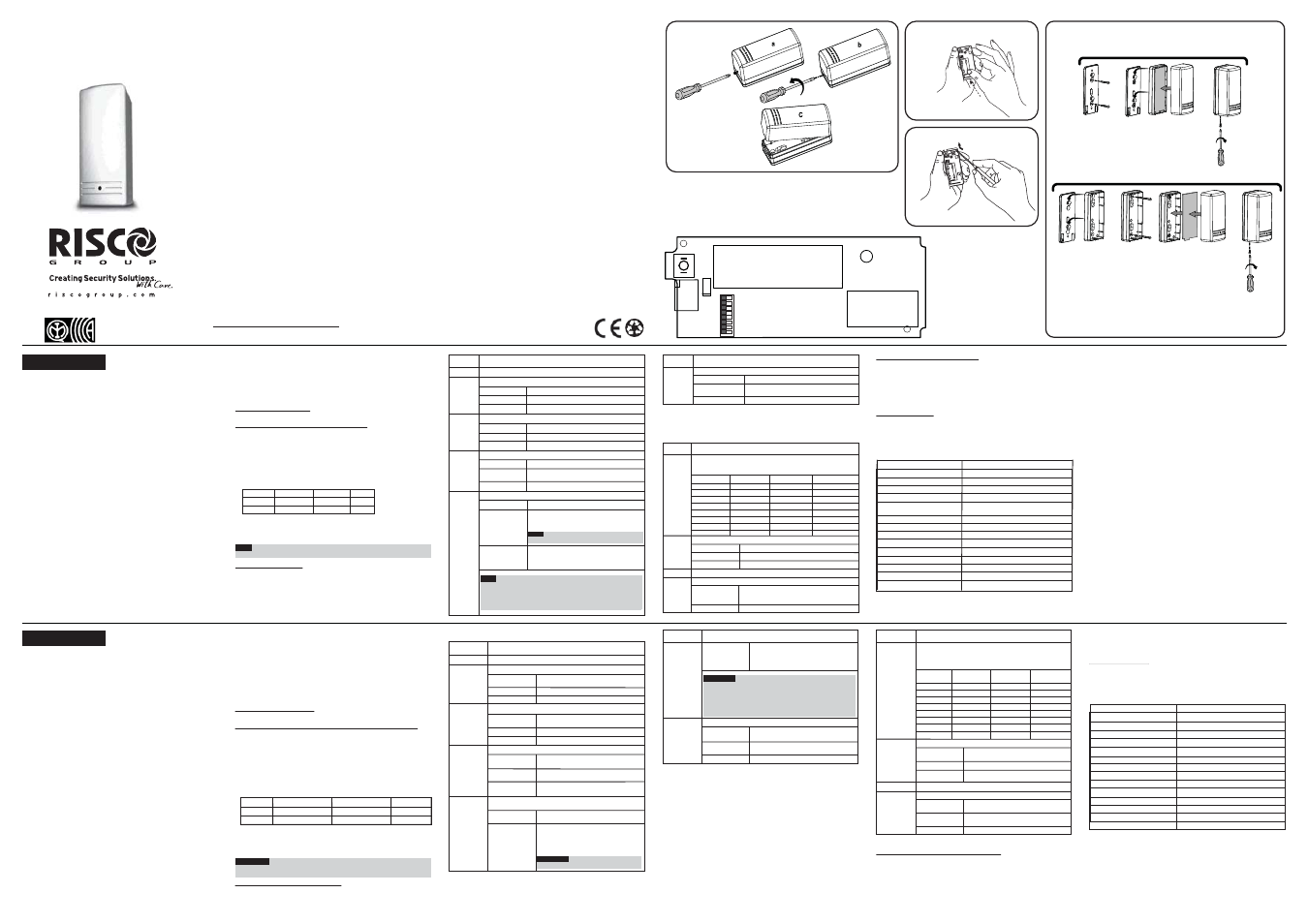
Step 1: Front Cover Removal
Remove the front cover as described in Fig. 1.
Step 2:Transmitter/Receiver Communication Setup
The transmitter must identify itself to the system's receiver by writing its coded
message into the receiver's address memory. This is accomplished by
performing the following steps:
a. Set the receiver to Write Mode.
b. Remove the battery from the insulation material (fig. 2).
c. Set dipswitches 4 and 5 as described in the table below to choose the
transmitters function mode. All other dipswitches must be in the OFF
position during the learning mode.
d. Send a Write message pressing both tamper buttons for at least 3 seconds.
Verify that the transmitter has been identified by the receiver.
e. Set the receiver to Normal Mode.
Note:
If for any reason it is necessary to re-send a write message, press both
tamper buttons for at least 3 seconds.
Step 3: Dipswitch Settings
The transmitter has 8 dipswitchs which are configured differently according to
the operation mode as follows:
A: Universal Protection (Dipswitch 4 is OFF)
B: Shutter Protection (Dipswitch 4 is ON)
While the transmitter is in the Shutter protection mode, it operates as a non-
restorable transmitter. An alarm message is sent while the number of pulses
is more than were pre-set by the dipswitches.
Should any questions arise please contact your supplier.
Universal OFF ON
YES
Shutter ON ON NO
*Default
8
ON
OFF*
Dipswitch Position RF Power Transmission
RF high power
RF low power (when then transmitter is
closed to the receiver.)
Dipswitch
No.
Dipswitch
No.
Description
Used to determine the transmission power:
*Default
Used for setting the number of pulses for a shutter detector.
Set dipswitches 1-3 for the required number of pulses as shown in
the following table:
Used to determine the transmitter’s functionality.
Shutter Control
Universal Transmitter
Not used (OFF position)
RF Power Transmission
Used to determine the transmission power:
RF low power (when then transmitter is closed
to the receiver.)
Dipswitch 1
Dipswitch 2
Dipswitch 3
No. of Pulses
OFF
OFF
OFF
OFF
OFF
OFF
OFF
OFF
ON
ON
ON
ON
ON
ON
ON
ON
2
4
6
8
10
12
14
16
RF high power
1-3
4
5-7
8
ON
Dipswitch Position Transmitter operation mode
OFF*
ON
OFF*
Description
OFF
ON
OFF
ON
OFF
ON
OFF
ON
Not used (OFF position)
Used to determine the contact mode.
1-3
6
Used to determine the response time.
Used to determine the HOLD status of the universal transmitter.
7
Hold is Off: No dead time between alarm
detection transmissions (the unit transmits
after each detection).
Dipswitch Position
ON
Shutter Control
Universal Transmitter
OFF*
Dipswitch Position
ON*
Contact Mode
Normally Open (NO)
OFF
ON
Slow: 500 ms (For operation with magnetic
contacts, etc.)
Dipswitch Position Response Time
Fast: 10 ms (For operation with a shock sensor)
OFF*
Used to determine the transmitter’s operation mode.
Transmitter operation mode
ON
Hold is On: There will be 2.5 minutes dead time
between the alarm detection transmissions.
(Restore messages will be sent immediately).
Note:
Only one alarm message is transmitted
in any 2.5 minute period.
Note:
In both HOLD status the following occurs:
1. Disconnecting the detector’s input terminal will send an alarm
after 500 ms.
2. Reopening and closing the detector inputs will generate an
extra alarm and restore messages.
OFF*
Dipswitch Position Hold Status
Normally Closed (NC)
Dipswitch
No.
Description
4
5
F R A N Ç A I S
1. Description générale
Les WL 72P est un transmetteur supervisés pouvant être reliés à des
contacts externes (protection universelle) ou à des contacts spéciaux
avec câble pour obturateur.
Il fonctionne avec les récepteurs RISCO Group et alimenté par une
pile lithium 3Volts standard.
Principales caractéristiques du transmetteur
• Portée de fonctionnement jusqu'à 300 m (1000gt.) (en extérieur),
Puissance RF élevée/ faible,
Pour l'installation, utilisation de l'une des plus de 16 millions d'adresses
codées, préréglées et sélectionnées de manière pseudo-aléatoire,
Conception microprocesseur,
Extension de la durée de vie de la pile,
Entièrement supervisé,
Fonction sélective (protection universelle ou obturateur),
Compteur de pulses sélectif (pour la fonction de contrôle de l'obturateur),
Temps de réaction sélectif et entrée (NO/NF) pour fonction de contrôle
universelle,
Protection anti-sabotage (Autoprotection) arrière et couvercle.
•
•
•
•
•
•
•
•
•
2. Modes Fonction en option
Le transmetteur dispose de 2 modes Fonction, réglés selon la position du
commutateur DIP 4 :
Contrôle de l'obturateur (commutateur DIP en position de marche (ON),
Contrôle universel (commutateur DIP en position d'arrêt (OFF)
3. Modes d'exploitation de la protection universelle
NORMAL :
le transmetteur envoie un message d'alarme lorsqu'il se
déclenche; une fois rétabli, il transmet un message de restauration.
Un seul message d'alarme à la fois est transmis sur un intervalle de 2,5
minutes.
1. Des messages supplémentaires de restauration peuvent être générés en
rouvrant et fermant les entrées.
2. La déconnexion/ la coupure du terminal d'entrée entraîne une alarme
(après 500ms).
ECRITURE:
un message écrit est transmis par pression sur les deux
boutons d'autoprotection pendant au moins 3 secondes.
1. L'appareil envoie un message de supervision toutes les 15/65 minutes,
indiquant l'état de l'entrée et celui de la pile.
2. Lors de l'installation ou du remplacement, exécutez un test de
communication avec le récepteur pour en vérifier le bon fonctionnement.
4. Indicateurs LED
Après chaque détection, les indicateurs LED s'allument momentanément.
En cas de pile faible (batterie fable) – le voyant LED clignote 3 fois à chaque
transmission.
5. Installation du transmetteur
Etape 1 : Retrait du couvercle
Retirez le couvercle frontal comme l'indique le schéma en fig. 1.
Etape 2 : Etablissement de la communication Transmetteur/ Récepteur
Le transmetteur doit s'identifier auprès du récepteur du système en inscrivant
son message codé dans le registre d'adresses du récepteur. Cette opération
s'accomplit en exécutant les étapes suivantes :
a. Réglez le récepteur en mode écriture.
b. Retirez la pile de sa protection (fig. 2).
c. Réglez les commutateurs DIP 4 et 5 selon les instructions du tableau
ci-dessous pour choisir le mode Fonction du transmetteur. Tous les autres
commutateurs DIP doivent être en position d'arrêt (OFF) pendant la
période d'apprentissage.
Mode
Commutateur DIP 4
Commutateur DIP 5
Restauration
Universel
Arrêt (OFF)
Marche (ON)
OUI
Obturateur
Marche (ON)
Marche (ON)
NON
d. Envoyez un message écrit en appuyant sur les deux boutons
d'autoprotection pendant au moins 3 secondes. Vérifiez que le transmetteur
a bien été identifié par le récepteur.
e. Réglez le récepteur en mode normal.
Remarque :
Si pour une raison quelconque, il s'avère nécessaire de renvoyer
un message écrit, appuyez sur les deux boutons d'autoprotection pendant au
moins 3 secondes.
Etape 3 : Réglage des commutateurs DIP
Le transmetteur dispose de 8 commutateurs DIP dont la configuration diffère
selon le mode de fonctionnement, comme suit :
A : Protection universelle (Commutateur DIP 4 en position d'arrêt (OFF)
B : Obturateur (Commutateur DIP en position de marche (ON)
Lorsque le transmetteur est en mode de protection obturateur, il fonctionne
comme un transmetteur qui ne peut être rétabli.
Un message d'alarme est envoyé quand le nombre de pulses est supérieur à
celui préréglé par les commutateurs DIP.
Etape 4 : Choix ce l'emplacement de l'installation
a. Choisissez l'emplacement le mieux adapté pour assurer la qualité de la
communication, tout en restant près du détecteur filaire voulu (pour capteur
à liaison commutée).
b. Fixez provisoirement l'appareil en ce point à l'aide d'un ruban adhésif double
face.
c. Générez un signal d'alarme (en ouvrant ou en fermant momentanément les
terminaux d'entrée) et vérifiez que le récepteur a bien reçu le signal. Si le
signal d'alarme n'est pas détecté, replacez le transmetteur et essayez à
nouveau.
Etape 5 : Montage final
Séparez la partie arrière du transmetteur (fig. 3) et placez correctement toutes
ses pièces (fig. 4).
Si besoin est, reliez le capteur aux terminaux (ou bornes de connexion) d'entrée.
Ces spécifications sont susceptibles d'être modifiées sans avis préalable.
Pour tout renseignement, veuillez contacter votre revendeur.
Inutilisés (position d'arrêt (OFF)
Sert à déterminer le mode de contact.
1-3
6
Sert à déterminer le temps de réaction.
Sert à déterminer la position d'ATTENTE du transmetteur
universel.
7
Position du
commutateur DIP
Marche (ON)
Arrêt (OFF)*
Mode de contact
Normalement fermé (NF)
Normalement ouvert (NO)
Lent : 500 ms (en fonctionnement avec des
contacts magnétiques, etc.)
Rapide : 10 ms (en fonctionnement avec
un capteur de chocs).
Temps de réaction
Sert à déterminer le mode de fonctionnement du transmetteur.
Mode de fonctionnement du transmetteur
Contrôle de l'obturateur
Transmetteur universel
L'option d'Attente est active : un temps
mort de 2,5 minutes sera respecté entre
les transmissions de détection d'alarme.
(Des messages de restauration seront
envoyés immédiatement).
Remarque :
Une seule alarme est
transmise sur une période de 2,5 minutes).
Positon d'ATTENTE
Commutateur
DIP n°
Commutateur
DIP n°
Commutateur
DIP n°
Description
4
5
Position du
commutateur DIP
Marche (ON)
Arrêt (OFF)*
Position du
commutateur DIP
Marche (ON)
Arrêt (OFF)*
Position du
commutateur DIP
Marche (ON)
7
L'option d'Attente est inactive : pas de
temps mort entre les transmissions de
détection d'alarme (l'appareil émet après
chaque détection).
Remarque :
dans les deux cas :
1. La déconnexion du terminal d'entrée du détecteur lancera
une alarme après 500 ms.
2. La réouverture et la fermeture des entrées du détecteur
génèrera une alarme supplémentaire ainsi que des
messages de restauration.
Description
Arrêt (OFF)*
Sert à déterminer la puissance de transmission.
8
Position du
commutateur DIP
Marche (ON)
Arrêt (OFF)*
Transmission de puissance RF
Faible puissance RF (lorsque le
transmetteur est fermé au récepteur).
Puissance RF élevée
* Option sélectionnée par défaut
* Option sélectionnée par défaut
Servent à régler le nombre de pulses pour un détecteur à
obturateur.
Réglez les commutateurs DIP 1 -3 sur le nombre de pulses
requis comme l'indique le tableau suivant :
Sert à déterminer la fonctionnalité du transmetteur.
Contrôle de l'obturateur
Transmetteur universel
Inutilisés (position d'arrêt (OFF)
Sert à déterminer la puissance de transmission.
Transmission de puissance RF
Faible puissance RF (lorsque le
transmetteur est fermé au récepteur).
Puissance RF élevée
commutateur
DIP 1
1-3
4
5-7
8
Mode de fonctionnement du transmetteur
Arrêt (OFF)
Arrêt (OFF)
Arrêt (OFF)
2
Marche (ON) Arrêt (OFF)
Arrêt (OFF)
4
Arrêt (OFF) Marche (ON)
Arrêt (OFF)
6
Marche (ON) Marche (ON)
Arrêt (OFF)
8
Arrêt (OFF)
Arrêt (OFF)
Marche (ON)
10
Marche (ON) Arrêt (OFF)
Marche (ON)
12
Arrêt (OFF) Marche (ON) Marche (ON)
14
Marche (ON) Marche (ON) Marche (ON)
16
Description
commutateur
DIP 2
commutateur
DIP 3
commutateur
DIP 4
Position du
commutateur DIP
Marche (ON)
Arrêt (OFF)*
Position du
commutateur DIP
Marche (ON)
Arrêt (OFF)*
Wireless Pulse
Count Transmitter
WL 72P
© RISCO Group 12/14 5IN1298 D
Fig. 1
RISCO Group Limited Warranty
RTTE Compliance Statement
Hereby, RISCO Group declares that this product is in compliance with the
essential requirements and other relevant provisions of Directive 1999/5/EC.
The Declaration of Conformity may be consulted at www.riscogroup.com
Mode Dipswitch 4 Dipswitch 5 Restore
T.B
ON
3
1
2
4
5
6
7
8
DIPSWITCH
SW1
BATTERY
ANTENNA
+
-
C RISCO
3
4
CH1
CH2
LED
Fig. 2
Fig. 3
Fig. 1
Option A
Option B
RISCO Group and its subsidiaries and affiliates ("Seller") warrants its products to be free from defects in
materials and workmanship under normal use for 24 months from the date of production. Because Seller
does not install or connect the product and because the product may be used in conjunction with products
not manufactured by the Seller, Seller cannot guarantee the performance of the security system which
uses this product. Seller's obligation and liability under this warranty is expressly limited to repairing and
replacing, at Seller's option, within a reasonable time after the date of delivery, any product not meeting the
specifications. Seller makes no other warranty, expressed or implied, and makes no warranty of
merchantability or of fitness for any particular purpose. In no case shall seller be liable for any
consequential or incidental damages for breach of this or any other warranty, expressed or implied, or upon
any other basis of liability whatsoever. Seller's obligation under this warranty shall not include any
transportation charges or costs of installation or any liability for direct, indirect, or consequential damages
or delay. Seller does not represent that its product may not be compromised or circumvented; that the
product will prevent any personal injury or property loss by burglary, robbery, fire or otherwise; or that the
product will in all cases provide adequate warning or protection. Buyer understands that a properly
installed and maintained alarm may only reduce the risk of burglary, robbery or fire without warning, but is
not insurance or a guaranty that such event will not occur or that there will be no personal injury or property
loss as a result thereof. Consequently seller shall have no liability for any personal injury, property damage
or loss based on a claim that the product fails to give warning. However, if seller is held liable, whether
directly or indirectly, for any loss or damage arising under this limited warranty or otherwise, regardless of
cause or origin, seller's maximum liability shall not exceed the purchase price of the product, which shall
be complete and exclusive remedy against seller. No employee or representative of Seller is authorized to
change this warranty in any way or grant any other warranty.
NOTE
: This product should be tested at least once a week.
FCC ID: JE4RWT71X433
This equipment has been tested and found to comply with the limits for a Class B digital device, pursuant
to Part 15 of the FCC rules. These limits are designed to provide reasonable protection against harmful
interference in a residential installation. This equipment generates, uses and can radiate radio frequency
energy and, if not installed and used in accordance with the instructions, may cause harmful interference
to radio communications. However, there is no guarantee that interference will not occur in a particular
installation. If this equipment does cause harmful interference to radio or television reception, which can be
determined by turning the equipment off and on, the user is encouraged to try to correct the interference
by one or more of the following measures:
a) Reorient or relocate the receiving antenna.
b) Increase the separation between the equipment and receiver.
c) Connect the equipment to an outlet on a circuit different from that to which the receiver is connected.
d) Consult the dealer or an experienced radio/TV technician.
FCC Warning
The manufacturer is not responsible for any radio or TV interference caused by unauthorized modifications
to this equipment. Such modifications could void the user's authority to operate the equipment.
EN50131-1, EN50131-5-3, Grade 2 (G2),
Environmental Class II (EC2)
UK
Tel: +44-(0)-161-655-5500
E-mail: [email protected]
ITALY
Tel: +39-02-66590054
E-mail: [email protected]
SPAIN
Tel: +34-91-490-2133
E-mail: [email protected]
FRANCE
Tel: +33-164-73-28-50
E-mail: [email protected]
BELGIUM (Benelux)
Tel: +32-2522-7622
E-mail: [email protected]
U.S.A
Tel: +1-631-719-4400
E-mail: [email protected]
BRAZIL
Tel: +55-11-3661-8767
E-mail: [email protected]
CHINA (Shanghai)
Tel: +86-21-52-39-0066
E-mail: [email protected]
CHINA (Shenzhen)
Tel: +86-755-82789285
E-mail: [email protected]
POLAND
Tel: +48-22-500-28-40
E-mail: [email protected]
ISRAEL
Tel: +972-3-963-7777
E-mail: [email protected]
SPÉCIFICATIONS TECHNIQUES
ELECTRIQUES
Type de batterie (piles):
CR123, Pile lithium 3V
Consommation électrique:
30μA en veille; 13mA dans la transmission
Fréquence:
868,65 MHz / 433,92 MHz
Temps mort (ATTENTE):
2,5 minutes
Transmission de la supervision:
toutes les 15 minutes
Type de modulation:
ASK
Durée de vie de la pile:
5 ans (Sur l’utilisation)
PHYSIQUES
Dimensions:
81 X 35 X 32 mm (3,2 x 1,37 x 1,27 in.)
ENVIRONNEMENTALES
Immunité RF:
Selon EN50130-4
Température de fonctionnement: de 0°C à 55°C (32°F à 131°F)
Température de stockage:
de -20°C à 60°C (-4°F à 140°F)
Seuil de tension basse 2.5V
ELECTRICAL
Battery Type:
CR123, 3V Lithium Battery
Current Consumption:
30μA standby; 13mA transmission
Frequency:
868.65 MHz / 433.92 MHz
Dead Time (HOLD ON):
2.5 minutes
Supervision Transmission:
Every 65 minutes (for 433.92 MHz models)
Every 15 minutes (for 868.65 MHz models)
Modulation Type:
ASK
Battery Life:
5 years (Upon usage)
PHYSICAL
Size:
81 x 35 x 32 mm (3.2 x 1.37 x 1.27 in.)
ENVIRONMENTAL
RF immunity:
Operating temperature:
-10°C to 55°C (14°F to 131°F)
Storage temperature:
-20°C to 60°C (-4°F to 140°F)
Specifications are subject to change without prior notice.
According to EN50130-4
Low voltage threshold: 2.5V