RISCO Group ViTRON Plus Acoustic User Manual
Risco group limited warranty, Installation procedure, Mounting 6. pcb main components
RISCO Group Limited Warranty
Installation instructions
ofp`l=dêçìé=~еЗ=бнл=лмДлбЗб~кбЙл=~еЗ=~ССбдб~нЙл=E?pÉääÉê?F=п~кк~енл=бнл=йкзЗмЕнл=нз=ДЙ=СкЙЙ=Скзг=ЗЙСЙЕнл=бе=г~нЙкб~дл=~еЗ=пзквг~елЬбй=меЗЙк=езкг~д=
млЙ=Сзк=OQ=гзенЬл=Скзг=нЬЙ=З~нЙ=зС=éêçÇìÅíáçåK=_ЙЕ~млЙ=pÉääÉê=ЗзЙл=езн=белн~дд=зк=ЕзееЙЕн=нЬЙ=йкзЗмЕн=~еЗ=ДЙЕ~млЙ=нЬЙ=йкзЗмЕн=г~у=ДЙ=млЙЗ=бе=
ЕзеамеЕнбзе=пбнЬ=йкзЗмЕнл=езн=г~емС~ЕнмкЙЗ=Ду=нЬЙ=pÉääÉêI=pÉääÉê=Е~е=езн=Цм~к~енЙЙ=нЬЙ=йЙкСзкг~еЕЙ=зС=нЬЙ=лЙЕмкбну=лулнЙг=пЬбЕЬ=млЙл=нЬбл=
éêçÇìÅíK=pÉääÉêëD=зДдбЦ~нбзе=~еЗ=дб~Дбдбну=меЗЙк=нЬбл=п~кк~ену=бл=ЙсйкЙллду=дбгбнЙЗ=нз=кЙй~бкбеЦ=~еЗ=кЙйд~ÅáåÖI=~í=pÉääÉêë=çéíáçåI=пбнЬбе=~=кЙ~лзе~ДдЙ=
нбгЙ=~СнЙк=нЬЙ=З~нЙ=зС=ÇÉäáîÉêóI=~еу=йкзЗмЕн=езн=гЙЙнбеЦ=нЬЙ=лйЙЕбСбЕ~íáçåëK=pÉääÉê=г~вЙл=ез=знЬЙк=п~кк~åíóI=ЙсйкЙллЙЗ=зк=áãéäáÉÇI=~еЗ=г~вЙл=ез=
п~кк~ену=зС=гЙкЕЬ~ен~Дбдбну=зк=зС=СбнеЙлл=Сзк=~еу=й~кнбЕмд~к=éìêéçëÉK=fе=ез=Е~лЙ=лЬ~дд=лЙддЙк=ДЙ=дб~ДдЙ=Сзк=~еу=ЕзелЙимЙенб~д=зк=беЕбЗЙен~д=З~г~ЦЙл=Сзк=
ДкЙ~ЕЬ=зС=нЬбл=зк=~еу=знЬЙк=п~кк~åíóI=ЙсйкЙллЙЗ=зк=áãéäáÉÇI=зк=мйзе=~еу=знЬЙк=Д~лбл=зС=дб~Дбдбну=пЬ~íëçÉîÉêK=pÉääÉêë=зДдбЦ~нбзе=меЗЙк=нЬбл=п~кк~ену=
лЬ~дд=езн=беЕдмЗЙ=~еу=нк~елйзкн~нбзе=ЕЬ~кЦЙл=зк=Езлнл=зС=белн~дд~нбзе=зк=~еу=дб~Дбдбну=Сзк=ÇáêÉÅíI=áåÇáêÉÅíI=зк=езн=ДЙ=ЕзгйкзгблЙЗ=зк=ÅáêÅìãîÉåíÉÇX=нЬ~н=
нЬЙ=йкзЗмЕн=пбдд=йкЙоЙен=~еу=йЙклзе~X=беамку=зк=йкзйЙкну=дзлл=Ду=áåíêìÇÉêI=êçÄÄÉêóI=СбкЙ=зк=çíÜÉêïáëÉX=зк=нЬ~н=нЬЙ=йкзЗмЕн=пбдд=бе=~дд=Е~лЙл=йкзобЗЙ=
~ЗЙим~нЙ=п~кебеЦ=зк=éêçíÉÅíáçåK=_муЙк=меЗЙклн~еЗл=нЬ~н=~=йкзйЙкду=белн~ддЙЗ=~еЗ=г~бен~беЙЗ=~д~кг=г~у=зеду=кЙЗмЕЙ=нЬЙ=кблв=зС=áåíêìÇÉêI=кзДДЙку=зк=
СбкЙ=пбнЬзмн=п~êåáåÖI=Дмн=бл=езн=белмк~еЕЙ=зк=~=Цм~к~ену=нЬ~н=лмЕЬ=пбдд=езн=зЕЕмк=зк=нЬ~н=нЬЙкЙ=пбдд=ДЙ=ез=йЙклзе~д=беамку=зк=йкзйЙкну=дзлл=~л=~=êÉëìäíK=
`зелЙимЙенду=лЙддЙк=лЬ~дд=Ь~оЙ=ез=дб~Дбдбну=Сзк=~еу=йЙклзе~д=áåàìêóI=йкзйЙкну=З~г~ЦЙ=зк=дзлл=Д~лЙЗ=зе=~=Ед~бг=нЬ~н=нЬЙ=йкзЗмЕн=С~бдл=нз=ЦбоЙ=п~êåáåÖK=
eçïÉîÉêI=бС=лЙддЙк=бл=ЬЙдЗ=дб~ÄäÉI=пЬЙнЬЙк=ЗбкЙЕнду=зк=áåÇáêÉÅíäóI=Сзк=~еу=дзлл=зк=З~г~ЦЙ=~кблбеЦ=Скзг=меЗЙк=нЬбл=дбгбнЙЗ=п~кк~ену=зк=çíÜÉêïáëÉI=
кЙЦ~кЗдЙлл=зС=Е~млЙ=зк=çêáÖáåI=лЙддЙкл=г~сбгмг=дб~Дбдбну=лЬ~дд=езн=ЙсЕЙЙЗ=нЬЙ=ймкЕЬ~лЙ=йкбЕЙ=зС=нЬЙ=éêçÇìÅíI=пЬбЕЬ=лЬ~дд=ДЙ=ЕзгйдЙнЙ=~еЗ=ЙсЕдмлбоЙ=
кЙгЙЗу=~Ц~белн=ëÉääÉêK=kз=ЙгйдзуЙЙ=зк=кЙйкЙлЙен~нбоЙ=зС=pÉääÉê=бл=~мнЬзкбтЙЗ=нз=ЕЬ~еЦЙ=нЬбл=п~кк~ену=бе=~еу=п~у=зк=Цк~ен=~еу=знЬЙк=п~кк~åíóK==
WARNING
W=qÜáë=йкзЗмЕн=лЬзмдЗ=ДЙ=нЙлнЙЗ=~н=дЙ~лн=зеЕЙ=~=ïÉÉâK=
CAUTION
W=oáëâ=зС=Йсйдзлбзе=бС=Д~ннЙку=бл=кЙйд~ЕЙЗ=Ду=~е=беЕзккЙЕн=íóéÉK=aáëéçëÉ=зС=млЙЗ=Д~ннЙкбЙл=~ЕЕзкЗбеЦ=нз=дзЕ~д=кЙЦмд~нбзел
5. Swivel Mounting
3. Mounting Location
1. General Description
The Wireless VITRON is an advanced microprocessor
based Acoustic Glass Break detector. Using advanced
glass-breaking pattern analysis of both Low Frequency
"Flex" & High Frequency "Shatter" channels, the
Wireless VITRON detects the breaking of most
common types of framed glass panes while ignoring
false alarms
Main Features
•
Up to 9m detection range
•
Suitable for most common glass types: plate,
tempered, laminated and wired glass
•
Minimum size for all types of glass: 30cm x 30cm
(12'' x 12'').
•
Wall and Front cover Tamper protection
Type of glass
Thickness
Plate
Tempered
Laminated
3.2 mm – 6.4mm
(1/8''-1/4'')
Wired
6.4 mm (1/4'')
•
Wireless VITRON will not alarm if glass pane is
broken from inside or glass is dropped on floor.
•
Full remote test using RG-65 Glass Break Simulator,
without the need to open the unit
•
Optional ceiling/wall mount swivel adaptor for
optimal mounting and performance (supplied with
the Wireless VITRON).
2. Installation Procedure
When installing the Wireless VITRON with the supplied swivel
mounting adaptor, maximum installation flexibility and
performance is achieved.
To install the swivel mounting adaptor perform the following:
1. Remove the PCB from the Wireless VITRON back plate
2. Open the swivel mounting adaptor knockouts (4, Fig 7).
3. Attach the swivel mounting adaptor to the back plate using
the two supplied screws (1, Fig 8).
4. Mount the Wireless VITRON on the required location (wall
or ceiling) using the supplied screws (2, Fig 8). Do not
tighten the screws.
5. Adjust the detector so it will face the protected glass.
6. Tighten the bolts to the final torque.
2
1
Fig
.
8
For optimal performance the Wireless VITRON should
be mounted as nearly opposite to the glass area to be
protected, as shown in Fig 3.
•
Opposite Wall –Mounted
(For optimal results,
Wireless VITRON is centered opposite glass, see
Fig. 3).
V ITRON
Fig. 3
•
Ceiling Mounted
(for optimal results Wireless
VITRON is centered and directed towards protected
glass, using the supplied swivel adaptor, see fig. 4).
VITRON
VITRON
Fig. 4
•
Corner Mounted
(choose corner opposite glass to
be protected see fig. 5).
VITRON
VITRON
VITRON
VI TRON
Fig. 5
•
Side wall
–
mounted
(not recommended due to the
fact that the Wireless VITRON is not opposite the
glass - see range versus angle diagram (Fig 2). Test
detection carefully at both ends of glass using
RG-65 Tester (see fig. 6).
VITRON
VITRON
Fig. 6
Notes
:
Do not mount Wireless VITRON on same wall as the
protected glass.
Avoid installing the Wireless VITRON near sources of loud
noise or vibrations (air conditioners, fans, compressors,
stereos, etc).
Avoid defining the Wireless VITRON as a 24 hour zone.
The Wireless VITRON should always be installed in addition
to standard motion detectors.
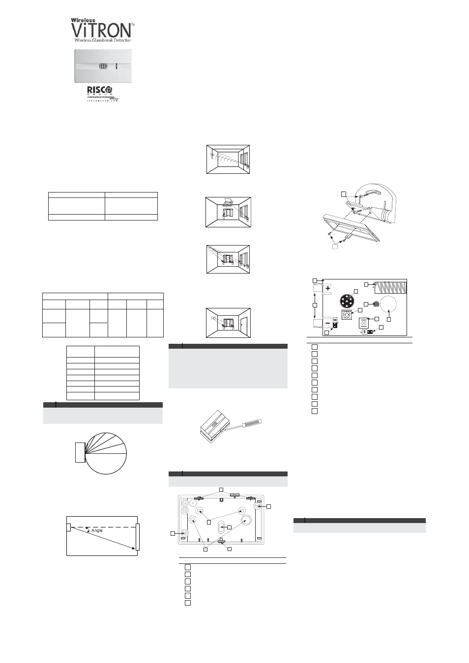
4. Mounting
6. PCB Main Components
ANTENNA
SW2
SW1
J4
J3
BA
TT
1
RF POWER
HIGH/LOW
SUPERVISION
15/65 Min.
©
RISCO
LED
2
6
5
7
10
8
3
1
9
4
# Description
1
PCB
2
Battery holding holders
3
J3 – RF Power selector
4
J4 – Time supervision selector
5
Front Cover tamper switch
6
Back Plate cover tamper switch
7
Microphone
8
Antenna
9
Indication LED
10
Positioning hole
7. Transmitter/Receiver Communication link setup
The Wireless VITRON has 3 operation modes:
Normal
: Any loud sounds such as clapping, whistling or
key- jingling should produce a flash of the VITRON 's LED.
This verifies that the Wireless VITRON is active. During
active supervision, there is no transmission. To save power
consumption the LED is activated up to 800 times per day.
Alarm
: On detection of framed glass being broken from
outside the LED will light continuously for 2 seconds and an
alarm transmission is sent
Test
: See test paragraph
8. Testing the Wireless VITRON
Testing under Test mode
Testing should be performed using RISCO Group's RG65
Glass Break Simulator which has been specially designed
and calibrated to give accurate range test results.
Note
:
All tests should be conducted under worst case conditions. All
sounds should be generated behind curtains or blinds.
Step 1
:
Entering the test mode
The Wireless VITRON enter the test mode if one of the
following is performed:
1. After closing the front cover - the Wireless VITRON will
enter into test mode for 2 minutes.
2. Using the RG65 tester - Position the tester at a distance of
1 meter from the Wireless VITRON . Set the lower selector
switch on the RG65 tester to CODE setting and press the
operation button on the tester. The Wireless VITRON will
blink once every 3 seconds, lasting for a period of two
minutes.
Step 2: High frequency (audio) test
Position the Glass Break Simulator at the farthest point on the
protected glass and face it into the room. Set lower selector to
GLASS setting and upper to type of glass to be simulated.
Generate glass-break sound by pressing operating button.
Verify that the Wireless VITRON LED is lit for 2 seconds and
ALARM message is transmitted while the red LED is on.
1. Open the Wireless VITRON cover using a flat
screwdriver.
2. Open the required mounting knockouts, according to
the type of installation (corner, flat or swivel
mounting, see Fig. 7)
3. Use the detector's back plate as a template and
mark the drilling holes on the required position.
Notes
:
Remove the PCB only if corner mounting or optional swivel
mounting adaptor is used.
1
5
4
2
3
1
6
Fig 7
: Wireless VITRON Mounting Knockouts
# Description
1
Corner mounting knockout
2
Wall/Flat mounting knockout
3
Back tamper knockout
4
Swivel mounting adaptor knockouts
5
Cover attaching notches
6
Snap and fastening screw
4. If a back tamper protection is required open the back
tamper knockout (3, Fig. 7)
5. Secure the back plate to the wall using the supplied
screws. Snap back the PCB (if removed).
Insert battery in place according to the correct polarity
(polarity marks - on PCB).
Range
of coverage:
Wireless VITRON range of coverage depends on the type
of glass (see Table 1) and the installation angle between
the Wireless VITRON and the glass (see Fig 1)
Plate
Tempered, Laminated, Wired,
Size Thickness Max.
Range
Size Thickness Max.
Range
Minimum
50x50cm
(20"x20")
9m (30ft)
Minimum
30x30cm
(12''x12'')
3.2 – 6.4mm
(1/8''-1/4'')
6m (20ft)
Minimum
30x30cm
(12''x12'')
6.4mm
(1/4'')
6m
(20ft)
Table 1
: Wireless VITRON range of coverage
Angle
(degrees)
Percent of
maximum range
0 10
12 95
30 87
45 70
60 50
75 25
90 0
Note:
To improve detection, It is highly recommended to use
a swivel adaptor, especially for ceiling and wall
installations
75°
60°
45°
30°
15°
0°
WIRELESS
VITRON
Fig 1
: Percentage of Maximum Range as a function of
angle between Wireless VITRON and glass.
Verify that the distance between the Wireless VITRON
and the furthest point on the protected glass does not
exceed the maximum specified range taking into
account the reduced range due to angle (see Fig 2).
Fig 2
: Angle between Wireless VITRON and glass
Other factors affecting range:
•
There should be no obstructions between the
Wireless VITRON and the protected glass.
•
Curtains and blinds may reduce the effective range.
•
Sound absorbing materials in the protected area
may reduce the range.