RIGOL DSA875 User Manual
Vb1040 vswr bridge, Product overview, Measurement connection
User Guide
RIGOL
Dec. 2012
VB1040 VSWR Bridge
Product Overview
VB1040 is used in combination with the RIGOL DSA series spectrum analyzer to measure
S11-related parameters (such as return loss, reflection coefficient and VSWR). VB1040
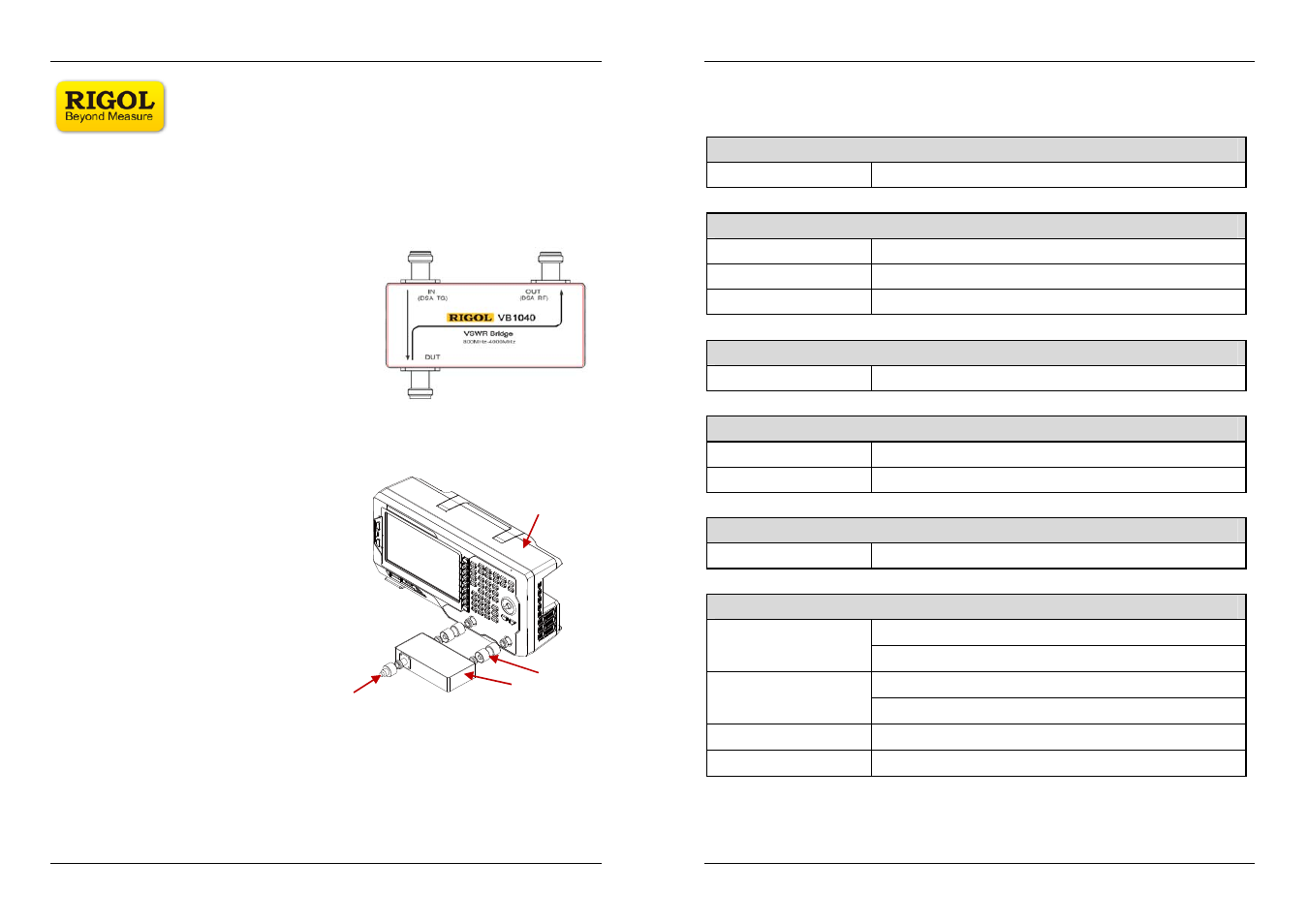
provides three N (Female) connectors as shown in the figure below.
—
IN: Signal input terminal. Here the signal
generator or the output terminal of the
tracking generator of the spectrum analyzer is
connected.
—
OUT: Signal output terminal. Here the power
meter or the RF input terminal of the spectrum
analyzer is connected.
—
DUT: Here the device under test is connected.
Measurement Connection
Connect VB1040 to the spectrum analyzer
as shown in the figure on the right.
—
Connect the spectrum analyzer
Use 2 Dual N (Male) adaptors to
connect the output terminal of the
tracking generator and the RF input
terminal of the spectrum analyzer to
the IN terminal and OUT terminal of
the VSWR bridge respectively.
—
Connect the device under test
Do not use cables or adaptors as far as possible to avoid additional reflection.
Typical Applications
—
Measurement of the S11-related parameters of the filter, amplifier, mixer, etc.
—
Resonant frequency and VSWR tests of the antenna.
VSWR Bridge
Spectrum Analyzer
Adapter
Connect the device under test
User Guide
RIGOL
Dec. 2012
Specifications
Frequency
Frequency range
800 MHz to 4 GHz
Connector
Connector type
N (Female) Type
Adaptor
Dual N (Male) Type
Impedance 50
Ω
Insertion Loss
IN to DUT
<1 dB (typical)
Directivity
Typ.
≥20 dB
Min. 15
dB
Input Power
Maximum Input Power
+27 dBm (0.5 W)
General Specifications
Dimensions
112 mm×103 mm×16.5 mm
256 mm×190 mm×43 mm (With Package)
Weight
0.5 kg
1.2 kg (With Package)
Operation Temperature
-20 ℃ to 80 ℃
Storage Temperature
-40 ℃ to 100 ℃