ROCKINGER RO 560 User Manual
Series ro, Fitting, Importa nt doc ument
T
Series RO
i
560
Fully automatic trailer coupling
with homologation 94/20/EC
Fully automatic
trailer coupling
for drawbar eyes 50 DI
N 7
4053,
EC 94/20 class D, I
SO 1
102,
drawbar eye RO
i
5
7005
IIn
nsstta
alllla
attiio
on
n a
an
nd
d
o
op
pe
erra
attiin
ng
g iin
nssttrru
uc
cttiio
on
nss
1. Fitting
1.1 Before installation
Note:
Please comply with the following when fitting coupling:
– applicable national regulations
– vehicle manufacturer’s specifications
– clearance for axial rotation of coupling head of at least
e 25h
The coupling is supplied ready to operate.
1.2 Installation
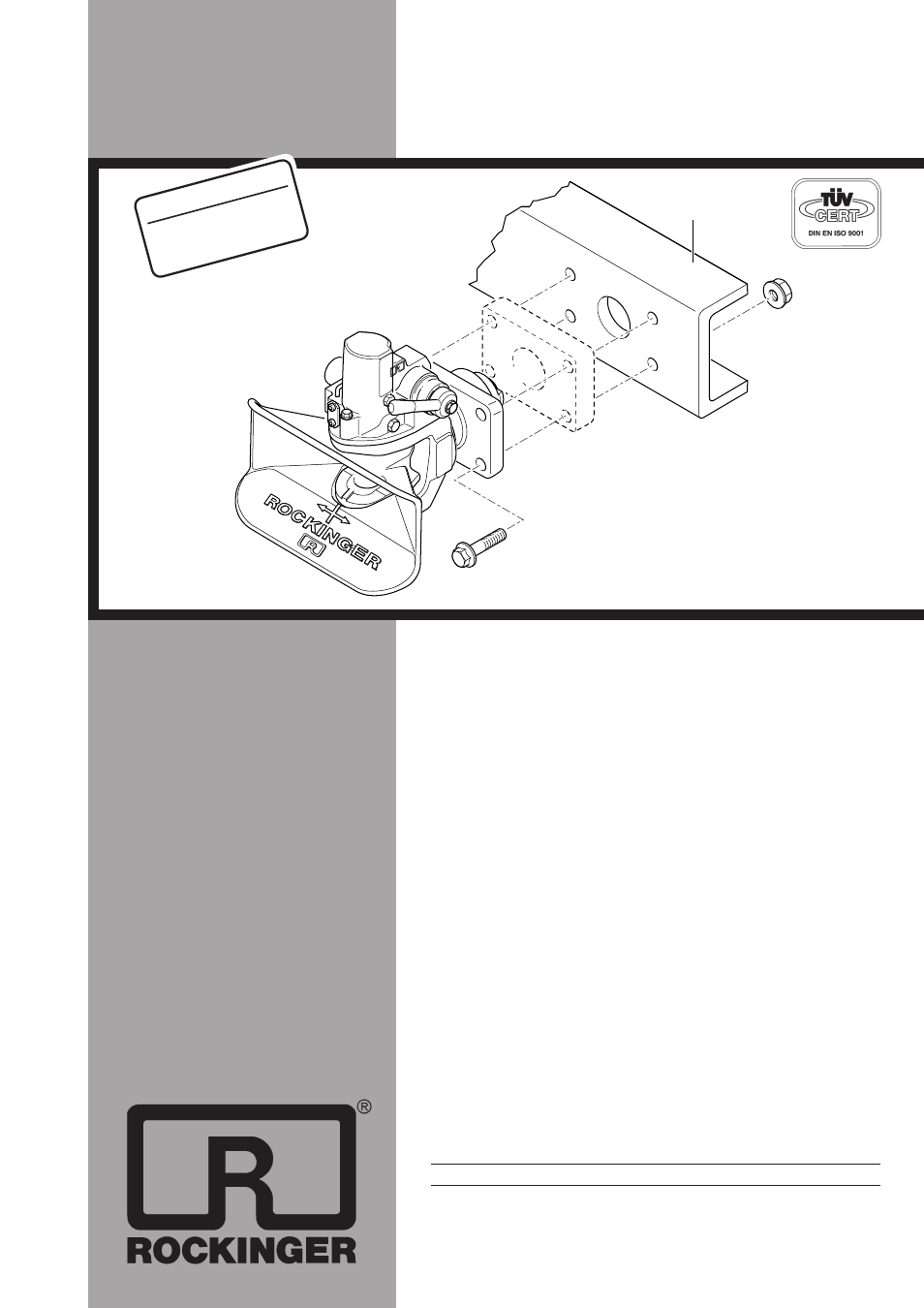
x Mounting plate must be mounted to the crossbar (T)
– Lead the cone into the middle of the hole from the crossbar
–
or
– use the interim plate (see Fig. 1, Ref. no. 71053)
– Agriculture- and forestry in connection with a suitable
–
ROCKINGER-coupling holder, mounting dimension 330 mm:
–
Mount the fastening bearing of the coupling on the coupling holder
–
–
70904 (with vertical load 2000 kg interim plate not permissible)
–
see page 4 too.
x Attach with:
– 4 hexagon head cap screws to DIN 931, grade 10.9
– 4 self-locking nuts to DIN 6925, grade 10
Please see table for details of nut and screw size.
Note:
Please comply with vehicle manufacturer’s specifications
regarding nut and screw grade if these differ from above!
Caution:
Bolt heads should be on coupling head side
(outer side of crossbar) to avoid impairing movability of coupling
(see Fig. 1)
Tightening torques when attaching screws to mounting plate:
coupling
screw
tightening
width across
size
size
torque (Nm)
flats S (mm)
6
M 20
725
30
Crossbars with holes through the entire surface
Grip corresponding to the crossbar design of the vehicle manufacturer, with
S = 2000 kg: min. grip 60 mm, load 430 N/mm
2
Note:
Before painting, it is essential to close coupling and grease or
cover coupling pin.
Importa
nt doc
ument!
must be handed to the
custom
er before the coupling
is mounted
!
Fig. 1
T
ype 560 U 6 e1 00-0404
class C 50-
X
KE 0
7
00 I
I 1
249-
G
B
As at 0
700
Subject to technical
changes without prior notice