Nigel B Design NB-PLWB User Manual
Plenum equipment box, Installation instructions
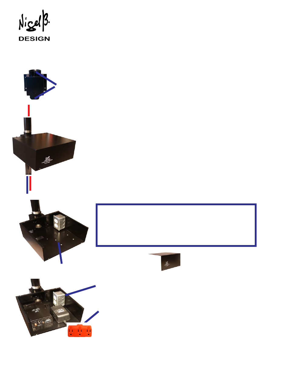
PLENUM EQUIPMENT BOX
TO CEILING SPEAKERS
The Power Cable's Conduit attaches to the Plenum Box using a Standard Conduit
Connector (Customer Supplied), with the wires teminating directly to the Single Gang
Receptacle Box inside.
UP TO SIX POWER OUTLETS
The amount of Power Outlets can be increased to
SIX
using up to two 3 Position Taps.
POWER CABLE INSTALLED IN CONDUIT
LINE IN FROM PROJECTOR
MEETS NEC CODE REQUIREMENTS* FOR THE SAFE INSTALLATION
OF
ANY*
OF OUR AMPLIFIERS IN THE PLENUM SPACE
INSTALLATION INSTRUCTIONS
Web Site: www.nigelbdesign.com. E-Mail: [email protected]
POWER SUPPLY TO THE PROJECTOR
Access to the inside for Installation and Servicing is simple, removing the 6 screws
makes it very simple for a technician to make adjustments at any time.
1. The Pole Mount screws between two lengths of 1 1/2” Projector Poles, and can be
Locked using (2) 8.32 x 3/8" Screws. Once installed, the Plenum Box is then mounted
directly to the Pole Mount using the (4) 8.32 x 3/8" Pan Head Screws.
2. Power enters the Plenum Box at the side using Conduit to Code.
3. The Conduit is connected to the Plenum Box using a standard Conduit Connector
(not supplied).
4. Power Cables run inside the Bottom Pole directly to the Projector.
5. Line out from the Projector is run the same way.
6. Speaker Cables use the Upper Pole.
SUPPLIED PARTS
1. Heavy Duty Pole Mount with (4) 8.32 Truss Head Screws
2. (2) 8.32 x 3/8" Screws to lock Pole Mount to Projector's Pole
3. Plenum Box with Removable Cover with (6) 8.32 Pan Head Screws.
4. Single Gang Box with 2 Position Receptacle
5. (1) 10.32 x 5/8" Round Screw for Mounting Recepticle Box to Plenum Box
6. Receptacle Cover Plate
ADDITIONAL SIGNAL INLET/OUTLET PORT
An additional Cable Port (which is normally fitted with a Removable Blanking Cap)
is provided in the Pole Mount for those occasions when access to other equip-
ment is required.
* In compliance with NEC Article 300.22c when External Wiring Connections to the Box are in
made in accordance with those requirements.
REMOVABLE COVER
AMPLE SPACE FOR ADDITIONAL
EQUIMENT TO BE INSTALLED INSIDE
PIPE INSTALLATIONS
.
(2) 8.32 x 3/8" Screws are provided to be able to lock the Mount to each section of Pipe.
The Box (with the Cover removed) is then attached to the Mount using 4 Screws. The
Amplifier, Power Supply or any Equipment including the 1 Gang Receptacle are then
installed inside the Box together with all relevant Cables. Attaching the Cover completes
the installation.
INSTALLING THE EQUIPMENT BOX BELOW THE CEILING TILES
GENERAL INSTRUCTIONS
Nigel B Design, Inc. California, USA. Tel: (818) 487-9323 Fax: (818) 766-9805
* Including many other Equipment Manifacturers such as Crestron® , AMX® and Extron ®
The Plenum Equipment Box uses Standard 1 1/2" Pipe and Fittings.
These are
usually suplied with the Projector Mount or if not using a Projector, 1 1/2"
Pipe can be easily obtained from any Plumbing Supply.
The Plenum Equipment Box can also be placed below the Ceiling.
POLE MOUNT VERSION - PART # NB-PEBPM
LOCKING SCREWS