Others – Sharp PN-60TW3 User Manual
Page 51
51
E
Controlling the Monitor with a PC (RS-232C)
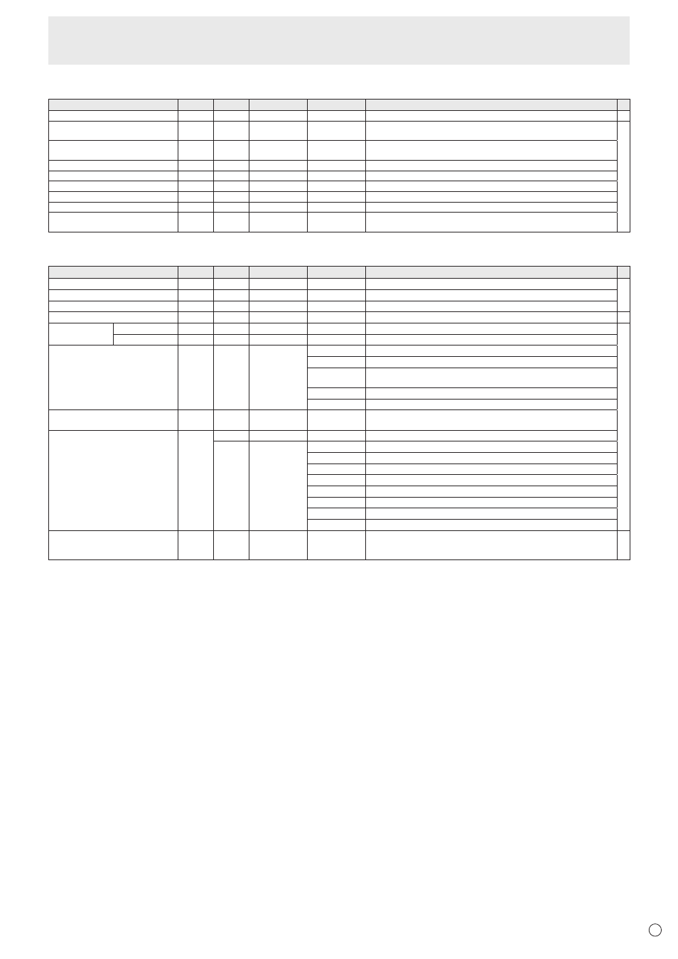
Initialization/Functional Restriction Setting (FUNCTION) menu
Function
Command Direction
Parameter
Reply
Control/Response contents
*
ALL RESET
RSET
W
0-1
0: ALL RESET 1, 1: ALL RESET 2
-
ADJUSTMENT LOCK
ALCK
WR
0-2
0-2 0: OFF, 1:ON1, 2:ON2
When POWER SAVE MODE is set to ON, ON2 cannot be selected (ERR).
○
ADJUSTMENT LOCK TARGET
ALTG
WR
0-2
0-2 0: REMOTE CONTROL, 1: MONITOR BUTTONS, 2: BOTH
“ERR” when OFF is selected for ADJUSTMENT LOCK.
OSD DISPLAY
LOSD
WR
0-2
0-2 0: ON1, 1: OFF, 2: ON2
LED
OFLD
WR
0-1
0-1 0: ON, 1: OFF
TEMPERATURE ALERT
TALT
WR
0-2
0-2 0: OFF, 1: OSD & LED, 2: LED
STATUS ALERT
SALT
WR
0-2
0-2 0: OFF, 1: OSD & LED, 2: LED
POWER BUTTON
PBTN
WR
0-1
0-1 0: MONITOR, 1: EXT. CONTROLLER
EXTERNAL CONTROLLER INPUT
PCIP
WR
0-5
0-5 0: D-SUB1, 1: D-SUB2, 2: DisplayPort, 3: HDMI1, 4: HDMI2, 5: HDMI3
“ERR” when MONITOR is selected for POWER BUTTON.
Others
Function
Command Direction
Parameter
Reply
Control/Response contents
*
SCREEN SIZE (PC)
WIDE
WR
0-5
0-5 0: Toggle to change size, 1: WIDE, 2: NORMAL, 3: Dot by Dot, 4: ZOOM1, 5: ZOOM2
○
SCREEN SIZE (AV)
WIDE
WR
0-5
0-5 0: Toggle to change size, 1: WIDE, 2: ZOOM1, 3: ZOOM2, 4: NORMAL, 5: Dot by Dot
VOLUME
VOLM
WR
0-31
0-31
MUTE
MUTE
WR
0-1
0-1 0: OFF, 1: ON
-
INFORMATION
MODEL
INF1
R
Value
○
SERIAL NO
SRNO
R
Value
TEMPERATURE SENSOR
DSTA
R
0 Internal temperature normal
1 Internal temperature abnormal has occurred and the monitor is in standby mode
2 Internal temperature abnormal occurred (To delete the information of temperature
abnormal, turn off the main power.)
3 Internal temperature abnormal has occurred and backlight brightness is dimmed
4 Temperature sensor abnormal
TEMPERATURE ACQUISITION
ERRT
R
Value Returns the temperature at the temperature sensors.
Indicates a temperature sensor abnormality when “126” is returned.
CAUSE OF LAST STANDBY MODE
STCA
W
0
Initialization
R
0 No detectable error has occurred
1 Standby mode by POWER button
2 Main power off by the main power switch
3 Standby mode by RS-232C or LAN
4 Input signal waiting mode by No Signal
6 Standby mode by abnormal temperature
8 Standby mode by SCHEDULE setting
20 Standby mode by OFF IF NO OPERATION setting
Touch operation valid/invalid
TPEN
WR
0-1
0-1 0: Invalid, 1: Valid
“ERR” when TOUCH INPUT SELECT is set to INVALID or the touch panel is not
connected.
-