SMA SC 500CP-10-JP Maintenance Manual User Manual
Page 15
SMA Solar Technology AG
5 Maintenance under Voltage Conditions
Maintenance Manual
SCCP-JP-WA-A4-en-12
15
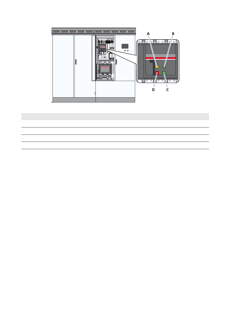
Figure 2: Indicators and switches on the DC load-break switch
Requirements:
☐ Control voltage is present.
☐ DC voltage is present.
Procedure:
1. Switch the inverter to Stop.
2. Open the doors of the interface cabinet.
3. Check whether the DC load-break switch is switched off and is indicating the Off position.
If the DC load-break switch is not switched off or indicating the Off position, contact the SMA Service Line.
4. Close the doors of the interface cabinet.
5. Switch the inverter to Start.
6. Open the doors of the interface cabinet.
7. Check whether the DC load-break switch is switched on and or indicating the On position.
If the DC load-break switch is not switched on or indicating the On position, contact the SMA Service Line.
8. Switch the inverter to Stop.
9. Close the doors of the interface cabinet.
Position
Designation
A
Spring status indicator
B
Position indicator
C
ON button
D
OFF button