Pads & trigger signals, Ω¡ ¡£ω, Œ› ∂∂‘á – Yamaha DTX-Multi12 Multi-Pad Electronic Percussion Instrument User Manual
Page 28
28
Owner’s Manual
Internal Design
Pads & Trigger Signals
The DTX-MULTI 12 is played by striking any of the
twelve built-in pads and by striking and operating external
pads, foot switches, or other controllers connected via the
PAD jacks (
M
to
Q
), the HI-HAT CONTROL jack, and
the FOOT SW jack. Whenever you perform this type of
action, a trigger signal containing various items of perfor-
mance data, such as the strength with which the pad was
struck, will be produced. These trigger signals are deliv-
ered to a tone generator, which outputs the appropriate
sound in response.
■
Built-in Pads (1 to 12)
As shown below, each of the DTX-MULTI 12’s built-in
pads is assigned a unique number between 1 and 12. On the
various parameter-setting pages used to configure the
instrument, these numbers are presented in the format
to
as a means of identifying individual pads. Although
Pads 4 to 9 (main pads) and Pads 1 to 3 and 10 to 12 (rims)
are shaped differently, they all function in exactly the same
way. Whenever they are struck, the assigned voices, waves,
or patterns will be played.
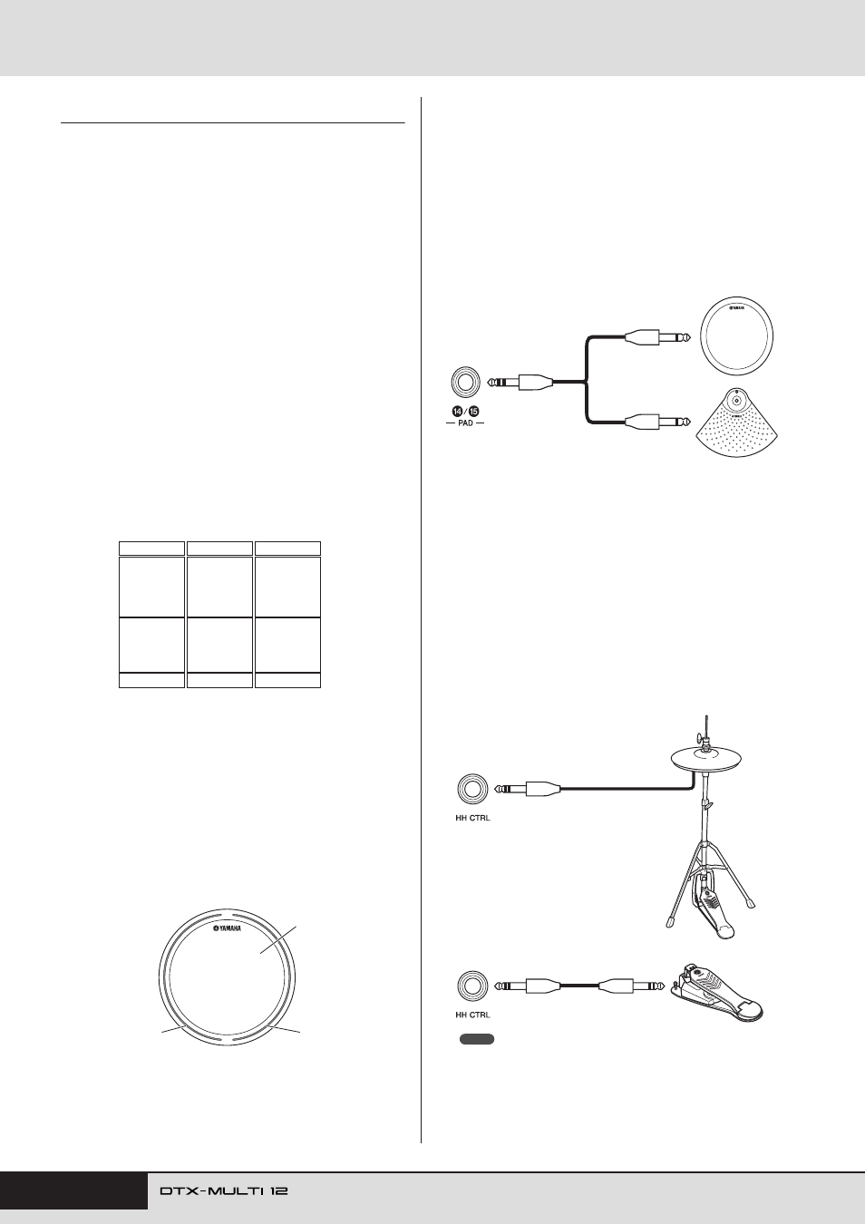
■
PAD Jacks (
M
to
Q
)
The trigger-input jacks provided on the rear panel are used
to connect optional pads. Furthermore, the PAD
M
jack
can be used to connect a three-zone pad, which produces
three different types of trigger signal based on the position
at which it is struck. The DTX-MULTI 12 treats these
zones as three individual pads, identifying them on-screen
as
,
, and
. For example, the three trig-
ger signals output by a TP65S Three Zone Drum Pad are
identified as shown below.
A: When a trigger signal from rim 1 is received, the voices assigned to
Pad
are played.
B: When a trigger signal from rim 2 is received, the voices assigned to
Pad
are played.
C: When a trigger signal from the head is received, the voices assigned
to Pad
are played.
Although each features just one connector, the PAD
N
/
O
and PAD
P
/
Q
jacks can be used to connect the mono out-
puts from a pair of pads. In this way, each of these jacks
can handle two different trigger signals. Within the display,
the numbers
,
,
, and
are used to identify
the corresponding pads.
■
HI-HAT CONTROL Jack
The Hi-hat Control jack is used to connect an optional
RHH135 Two Zone Hi-Hat Pad (via its HH CTRL jack) or
an HH65 Hi-hat Controller (via its OUTPUT jack). As you
play the pad or controller, the DTX-MULTI 12 receives
and recognizes trigger signals for both hi-hat close and hi-
hat splash*. Within the display, these signals are identified
as
and ,
respectively.
* Hi-hat splash refers to the technique of producing sound by rapidly
depressing and releasing the hi-hat pedal.
• Parameters related to hi-hats can be set on the various pages from the
UTILITY setting area’s HI-HAT section (UTIL5). (See page 89.)
º¡
¡™
¡º
¡¡
¡™
º¶
º•
ºª
º¢
º∞
º§
º¡
º™
º£
¡£ ¡£Ω¡
¡£Ω™
¡£Ω¡
¡£Ω™
¡£
A: Rim 1
B: Rim 2
C: Head
Example: TP65S
¡£Ω¡
¡£Ω™
¡£
¡¢ ¡∞ ¡§
¡¶
TP65
PCY65
When a trigger signal produced by striking the
TP65 Single Zone Drum Pad is received, the
voices assigned to Pad
are played.
¡¢
Example:
Connecting a TP65 and a PCY65 via the PAD
N
/
O
jack
When a trigger signal produced by striking the
PCY65 Single Zone Cymbal Pad is received, the
voices assigned to Pad
are played.
¡∞
∂∂œ›
∂∂‘á
HH65
RHH135
NOTE