Manuals
Directory
ManualsDir.com
- online owner manuals library
Search
Directory
Brands
FUJITSU manuals
Conditioners
RY-36UA
Manual
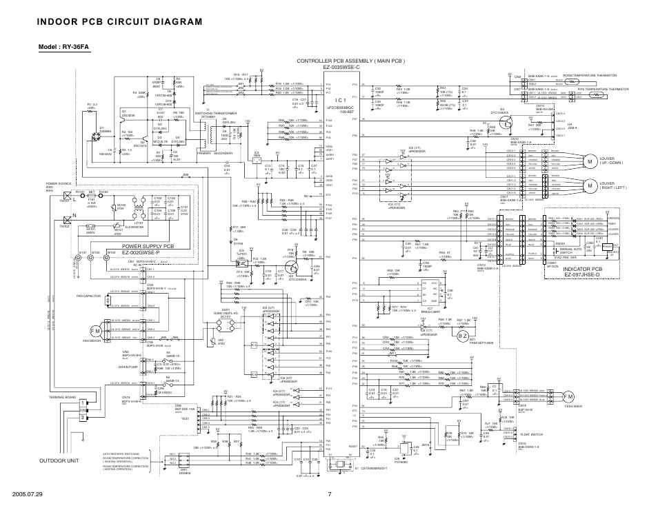
Indoor pcb circuit diagram, Model : ry-36fa, Indicator pcb ez-097jhse-d – FUJITSU RY-36UA User Manual
Page 8: Outdoor unit, Controller pcb assembly ( main pcb ) ez-0035wse-c, F m b z, Power supply pcb ez-002gwse-p, I c 1
Text mode
Original mode
Advertising
Indoor pcb circuit diagram, Model : ry-36fa, Indicator pcb ez-097jhse-d | Outdoor unit, Controller pcb assembly ( main pcb ) ez-0035wse-c, F m b z, Power supply pcb ez-002gwse-p, I c 1 | FUJITSU RY-36UA User Manual | Page 8 / 27
Share
Pages:
1
…
6
7
8
9
10
…
27
Download
Complain
wrong Brand
wrong Model
non readable
Advertising
This manual is related to the following products:
RO-36FA
,
RO-36UA
,
RY-36FA
Popular
Brands
Apple
Bissell
Brother
Canon
Casio
Cisco
Craftsman
Dell
FRIGIDAIRE
Garmin
GE
Honeywell
HP
John Deere
Kenmore
LG
Maytag
Motorola
NETGEAR
Nikon
Panasonic
Pioneer
Samsung
Sharp
SINGER
Sony
Whirlpool
Yamaha
All brands
Popular
manuals
Canon - AE-1
Fitbit - Flex
Nikon - D5000
Nikon - D40
Nikon - D3100
Nikon - D90
Nikon - D7000
Nikon - D80
Nikon - D3000
HP - Officejet Pro 8600
Canon - EOS 60D
HP - 12C Financial calculator
Full list