TAMKO TAM-RAIL User Manual
Tam-rail, Straight rail installation instructions
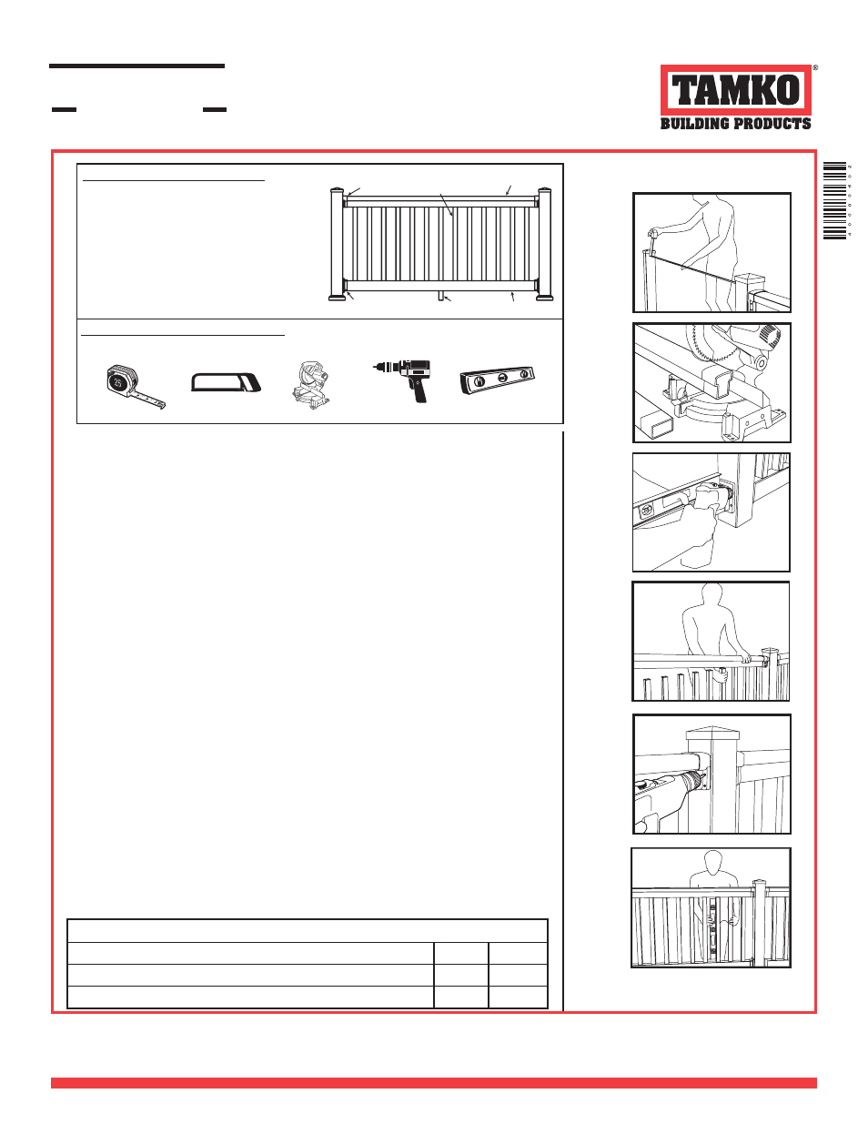
Straight Rail
Installation Instructions
Straight Rail Kit Components
• 6ʼ or 8ʼ TAM-RAIL Top Rail
• 6ʼ or 8ʼ TAM-RAIL Bottom Rail
• Balusters – Square or Colonial
• 6ʼ Square (13 ea.) or Colonial (14 ea.)
• 8ʼ Square (17 ea.) or Colonial (19 ea.)
• Brackets – Top Rail (2 ea.) Bottom Rail (2 ea.)
• 20 Coated Screws
• (17 ea.) 2 1/2” Stainless Steel Screws
• (3 ea.) 1 1/4” Stainless Steel Locking Screws
• 1 #3 Square Drive Bit
• Crush Block – 6ʼ Section (1 ea.) 8ʼ Section (1 ea.)
tape measure
hack saw
drill
level
Fig. 1
Fig. 2
Fig. 3
Fig. 4
Fig. 5
Fig. 6
ACTUAL STRAIGHT RAIL LENGTHS
Nominal Rail Length
6ʼ
8ʼ
Spaced for Colonial Balusters (Actual Rail Length)
70.5”
94.125”
Spaced for Square Balusters (Actual Rail Length)
72”
96”
.GH
GLLGE
JMK@
-IM9J=
GLLGE
.GH
miter saw
Tools Required For Installation -
Tape measure, miter saw or hack saw, #3 square
drive bit, power drill and level. For larger construction projects, miter saw and drill are
strongly recommended for quicker installation.
RAILING SYSTEMS
TAM-RAIL
®
10/07/08
JP55316
1. Install and prepare all mounting surfaces and posts to which new TAM-RAIL Railing will be installed. We sug-
gest using our innovative post mounting system or covering the wooden posts with our matching 3-layered post
sleeve.
2. Measure the inside opening between the posts or other mounting surfaces. NOTE: Confi rm the opening is
not wider than the length of the rails provided in TAM-RAIL Rail Kit. (FIG. 1)
3. Lay the bottom rail beside the posts or other mounting surfaces with the baluster holes facing upward. The
rail should extend past the mounting surface on each side. Be sure to place the fi rst baluster hole on each end
of the rail the same distance from the mounting surface. NOTE: If the baluster holes fall inside or directly be-
side a mounting surface, slide the rail approximately 2” in either direction to align baluster holes evenly
between mounting surfaces. When you have positioned your rail properly, mark and cut. (FIG.2)
4. Lay top rail beside bottom rail, making sure your baluster holes are aligned. Once properly aligned, mark and
cut to match bottom rail length. (FIG.2)
5. Locate the crush block (1 1/2” x 1 1/2” square profi le used to support the railing section) in your TAM-RAIL
Railing Kit. The formula for crush block length is: Desired clearance from bottom rail to deck + 3 1/4” =
length of crush block. NOTE: When using the TAM-RAIL New England Post Ring, you must cut your
Crush Block to a minimum of 5 1/2” to allow for proper spacing. Once the block is trimmed to appropriate
length, insert into precut hole on the underside of bottom rail. Be sure to check with your local building code
offi cials for any height requirements.
6. Slide mounting brackets onto bottom rail. Place bottom rail between posts or mounting surface making sure
crush block is fully nested in bottom rail and the bottom rail is level. Once the bottom rail height is determined,
mount brackets on the post or mounting surface and attach with provided 2 1/2” screws. NOTE: When install-
ing screws, pre-drill holes using a 1/8” drill bit. NOTE: If installing TAM-RAIL Railing into a masonry wall,
masonry screws must be used in place of screws provided in kit. (FIG.3)
7. Insert balusters into pre-routed holes in bottom rail. Balusters are available for 36” and 42” rail height kits
based on the traditional two-inch clearance from the bottom rail to the mounting surface. Note: Colonial and
Square balusters are available for 36” rail height kits; only Square balusters are available for 42” rail
height kits. Be sure to check with your local code offi cials for any height requirements.
8. Slide mounting brackets onto top rail. Place top rail on balusters inserting balusters one at a time while hold-
ing at an upward angle. Make sure balusters are completely nested in top rail and level. (FIG.4)
9. Center top rail over bottom rail and mount brackets onto post or mounting surface. Attach brackets with
provided 2 1/2” screws. (FIG.5)
10. Level balusters vertically and place 1 1/4” (provided) locking screw through the top bracket and into the top
rail. Repeat for bottom rail. NOTE: Only one side (top rail and bottom rail) needs to be secured. There are
extra (1 ea.) 1 1/4” and (1 ea.) 2 1/2” stainless screws provided. (FIG.6)
For assistance, information regarding, or to receive a
copy of TAMKO’s Limited Warranty, contact us at
1-800-641-4691 or visit us online at tamko.com.
It is the responsibility of the installer to meet all building code and safety requirements and to obtain all
required building permits. These instructions are only a guide and may not address every circumstance.
TAMKO Building Products Inc. shall not be held liable for improper or unsafe installations. These
application instructions were current at the time of printing. To obtain a copy of the most current version of
the application instructions, visit us online at tamrail.com or call us at 1-800-641-4691.