Nexen TCB07 835186 User Manual
Page 5
2
FORM NO. L-20169-D-0501
INSTALLATION
Do not flange mount the TCB-7. Flange
mounting will result in damage to the TCB-7
Housing.
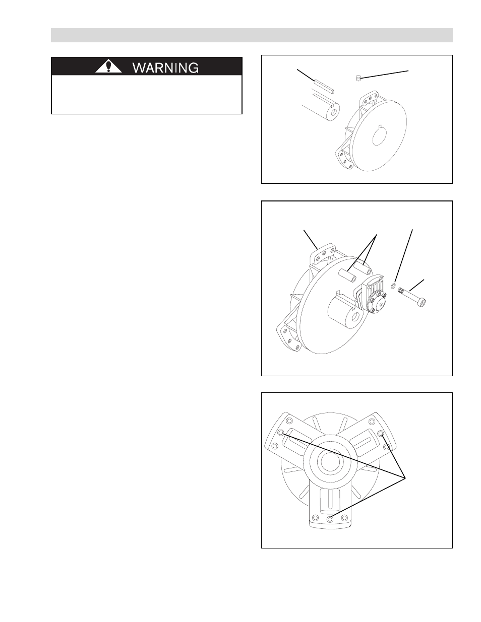
1.
Insert the Nexen supplied Key (Item 6) into the
machine shaft (See Figure 1).
2.
Slide the TCB-7 onto the machine shaft (See Figure 1).
3.
Tighten Set Screws (Item 3) to 7 Ft. Lbs. [9.5 N•m]
torque (See Figure 1).
NOTE: Runout of the Friction Disc Hub (Item 2)
must be less than 0.015'' [0.381 mm] TIR.
Runout is minimized if a dial indicator is used
as Set Screws (Item 3) are tightened. Place
contact tip of dial indicator on machined
surface of Friction Disc Hub to measure
runout.
4.
Using the Flat Head Screw (Item 10) provided with
the Friction Facing (Item 9), secure a Friction Facing
to each Caliper Assembly.
5.
Using the Spacers (Item 5), Lock Washers (Item 18),
and Socket Head Cap Screws (Item 19), secure
Caliper Assemblies to Housing (Item 1) (See Figure 2).
6.
Tighten Socket Head Cap Screws (Item 19) to 27 Ft.
Lbs. [36.4 N•m] torque.
NOTE: The TCB-7 is designed to be held from
rotation by an arm or a linkage sufficient to
prevent rotation, but loose enough to avoid
thrust loads on the bearing or brake housing.
7.
Using a customer supplied 5/16 UNC Cap Screw,
secure a Torque Arm to the TCB-7 to prevent
rotation of the TCB-7 (See Figure 3).
Key
(Item 6)
FIGURE 1
Housing
(Item 1)
Spacer
(Item 5)
Lock Washer
(Item 18)
Socket Head
Cap Screw
(Item 19)
FIGURE 2
Torque Arm
Anchoring
Points
FIGURE 3
Set Screw
(Item 3)