User operation guide – ABtUS AV382-V1 User Manual
Page 2
*Specifi cations are subject to changes without notice.
User Operation Guide
M4x45 screws
PACKAGING CONTENT
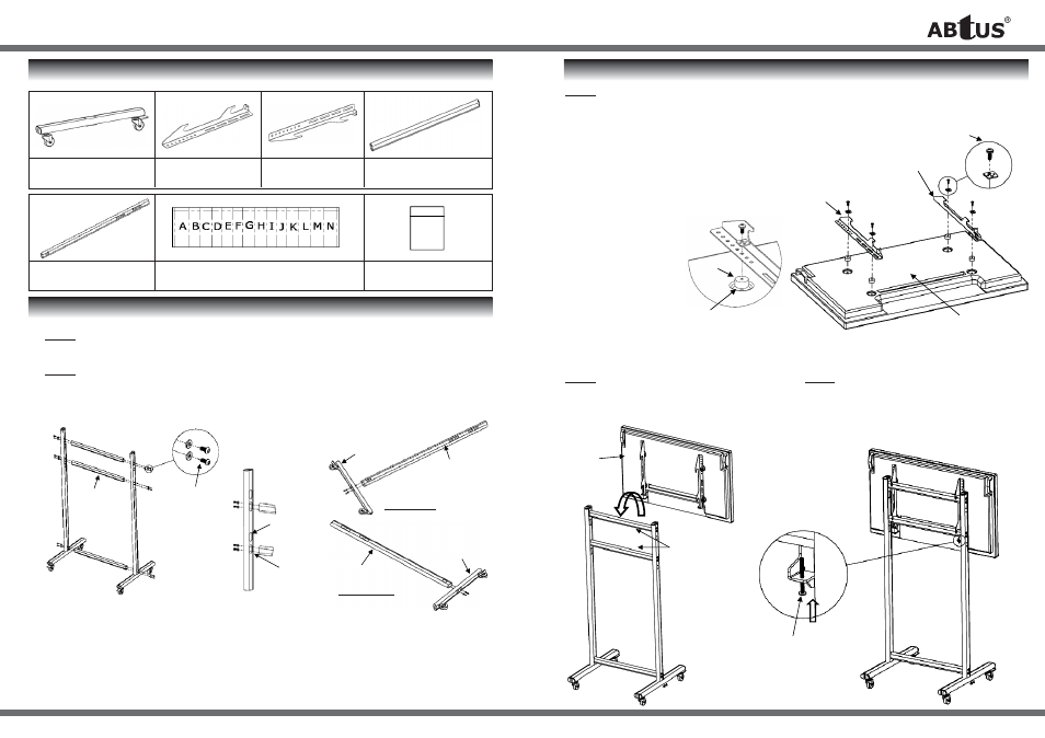
INSTALLATION
INSTALLATION
Item-1
Bottom Tube —1 sets
Item-5
Veritcal Tube —2 pcs
Item - 2
Hook right—1 pc
Item - 6
Screws bag 1 - 1 set
Item - 3
Hook Left—1 pc
Item - 4
Horizontal tube - 3pcs
Item - 7
Screws bag 2 - 1 set
Step-1 — assemble the Left Side Stand and Right Side Stand as shown in the diagram on the
right with M8x20 Button head Cap Screws and washers (in Item-7) provided.
Step-2 — join the Lfet Side Stand and Right Side Stang done in Step-1 as shown in the diagram
below with 3x Horizontal Yubes (item-4) with M8x15 Button Head Cap Screws and washers
(item-7)
** Note:
A. use 1st set of holes for 1.7m (approx) viewing height.
B. used 2nd set of holes for 1.6m (approx) viewing height.
Item-4
M8x15
Button
head cap
screw and
washer
1st set of
holes
Item-1
2nd set of
holes
Item-5
Item-5
Item-1
Left Side Stand
Right Side Stand
mounting
Spacer
Recess mounting
hole surface
Hook left
Hook right
Screw and
Square washer
Back of Plasma
Plasma
with
Hooks
Horizontal
tubes
Step-3 — Fix Hook right (Item-2) and Hook left (Item-3) onto back of
Plasma with screws and square washers (in Item-6) provided.
* Note: if screws provided can’t fit, please refer to the Plasma TV user
manual for the correct mounting thread screw.
** Use Spacers (in Item-6) for Plasma with recess mounting hole
surface
Step-4 — lift and hook the Plasma with Hooks
done in Step-3 onto the top Horizontal tubes
of the stand.
Step-5 — position the Plasma at the center of
the stand. Secure with M4x45 screws
(in Item-7)