Applied Motion 2035 User Manual
Connecting the motor, Connecting logic, Is this the right manual
Flip Over
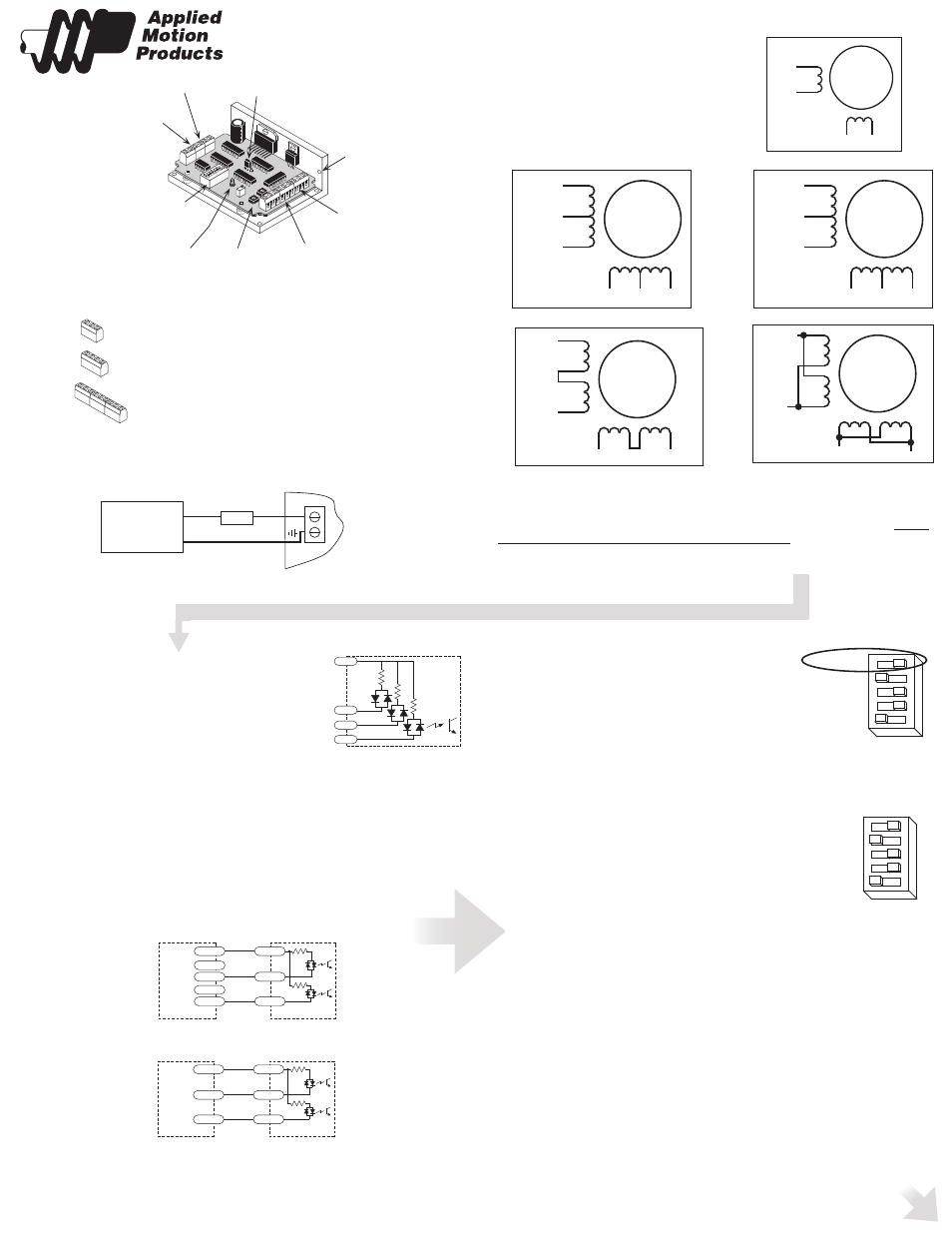
Connecting the Motor
STEP motors have 4, 6 or 8 leads , these are
wired to 4 connections on the drive in various
combinations.
Motors will perform differently according to the way
it is connected. To find out more about the different
ways of connecting your motor, see the specs or
FAQs on our website.
Warning: When connecting the motor to the driver, be sure that the motor
power supply is off. Secure any unused motor leads so that they can’t short
to anything. Never disconnect the motor while the drive is powered up. Never
connect motor leads to ground or to a power supply!
Connecting Logic
A schematic diagram of the input circuit is shown below.
Connect your logic circuitry to the signal connector as
shown in the sketch at the right. Even though the drive
provides it’s own 5 volt logic power, you must supply 5-24
volts DC to activate the LEDs on the input side of the
optoisolators. Most CMOS and open collector TTL devices
are directly compatible with this drive. If you are using
open collector outputs, no pull up resistor is necessary.
STEP tells the driver when to move the motor one step.
DIRECTION signals which way the motor should turn.
ENABLE allows the user to turn off the current to the motor by setting this signal to
logic 0.
If you have no need to disable the amplifiers, you don’t need to connect any-
thing to the ENABLE input.
Connecting to a controller with a differential output
Connecting to controller with a single ended output
Is This the Right Manual?
3 terminals - old 2035 or 2035 O. This is the wrong manual.
4 terminals - new 2035. This is the right manual.
9 terminals - new 2035 O. Right manual.
A+
A–
NC
B+
B–
NC
6
lead
motor
Red
Black
Red/
Wht
Green
Grn/Wht
White
6 Leads
Series
Connected
A+
A–
NC
B+
B–
NC
6
lead
motor
Grn/Wht
White
Green
Red
Red/
Wht
Black
6 Leads
Center Tap
Connected
A+
A–
B+
B–
8
lead
motor
8 Leads
Series
Connected
Orange
Org/Wht
Blk/Wht
Black
Red Red/
Wht
Yel/
Wht
Yellow
A+
A–
B+
B–
8
lead
motor
Orange
Org/
Wht
Blk/Wht
Black
Red
Red/Wht
Yel/
Wht
Yel
low
8 Leads
Parallel
Connected
Selecting Between Full and Half Step Operation
The top switch in the bank of DIP switches selects between
FULL and HALF step operation. The diagram shows the
drive in FULL step operation.
Setting Phase Current
The drive uses a combination or DIP switches to set the current. There is always a base
of current of 125 mA. To add to that, slide the appropriate switches toward their labels.
Example
Suppose you want to set the driver for 1.25 amps
per phase (1250 mA). You need the 125 mA base
current plus another 1000 and 125 mA.
1250 = 125 + 1000 +125
Slide the 125 and 1000 mA switches toward the labels
as shown in the figure.
HALF STEP
125
250
500
1000
logic
connector
STEP, DIR, EN
trimpots for adjusting
LED - indicates
DC power
oscillator speed, accel and
decel rates
(2035 O only)
mounting
hole (1 of 6)
power
connector
motor
connector
jumper for selecting
oscillator mode
(2035 O only)
switches for
selecting current,
idle current,
full or half stepping,
speed pot (2035 O)
connector for external
speed pot/signal
& tach output
(2035 O only)
A+
A–
B+
B–
4
lead
motor
Red
Blue
Yellow
White
4 Leads
COM
STEP
EN
DIR
Inside 2035
2200
2200
HALF STEP
125
250
500
1000
Quick Setup Guide
2035 & 2035-O
TO DOWNLOAD
A FULL
USER MANUAL
PLEASE VISIT OUR WEBSITE
WWW
.APPLIED-MOTION.COM
Connecting the Power Supply
12–35V
motor
supply
12-35 VDC
+
–
3A slow
blow
fuse
DO NOT REVERSE WIRES - THIS WILL DAMAGE THE DRIVE
+5 VDC
STEP–
STEP+
DIR–
DIR+
2035
COM
STEP
DIR
+5 VDC
STEP
DIR
2035
COM
STEP
DIR