Using the oscillator, Connecting logic – Applied Motion 2035 User Manual
Page 7
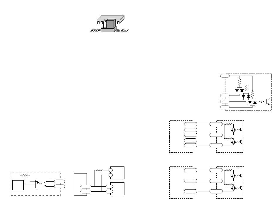
Using the Oscillator
Drives with an O suffix are equipped with internal
pulse generators that you can use to drive the motor.
To set the drive to oscillator mode, simply find the
jumper located near the center of the printed circuit
board and move it to the SLEW setting. The figure at the right shows the proper
setting of the jumper.
The oscillator is activated by driving the
STEP input low. The frequency of step
pulses will increase linearly, accelerating the motor until it reaches a preset speed.
The motor will remain at this speed until the
STEP input is driven high. The step
pulse frequency then decreases linearly, decelerating the motor and load to rest.
To change the slew speed, locate the trimpot labeled
SPEED. By turning the brass
screw you can raise or lower the speed within a range of 0 to 5000 steps per second.
Turning the screw clockwise makes the motor run faster.
The acceleration and deceleration rates can also be adjusted using the trimpots
labeled
ACCEL and DECEL. The range of accel and decel time is 5 to 900
milliseconds. Turning the pot clockwise makes the motor accelerate or decelerate
faster.
The ACCEL and DECEL pots are single turn, so don't try to turn
them too far.
COM
STEP
EN
DIR
Inside 2035
2200
2200
Connecting Logic
Internal Tach Circuit
Tach Output
The Tach Out signal is provided for measuring the motor speed. It generates one
pulse per motor step. The schematic diagram of the Tach Out optoisolation circuit
is shown below.
Do not connect the Tach output to more than 24VDC.
The current into the Tach+ terminal must not exceed 20 mA.
330
Ω
internal
tach
signal
+5V
TACH–
TACH+
Optoisolator
NEC PS2501 or equiv.
inside 2035 O
Connecting Tach Output
to a Frequency Counter
4700
Ω
5 - 24V
DC
Power
Supply
TACH–
TACH+
–
+
Freq
Counter
2035 O
GND
IN
-7-
-10-
The 2035 and 2035 O drives contain optical isolation circuitry to prevent the
electrical noise inherent in switching amplifiers from interfering with your circuits.
Optical isolation is accomplished by powering the motor driver from a different
supply than your circuits. There is no electrical connection between the two: signal
communication is achieved by infrared light. When your circuit turns on or turns off
an infrared LED (built into the drive) it signals a logic state to the phototransistors
that are wired to the brains of the drive.
A schematic diagram of the input circuit is shown below. Connect your logic
circuitry to the signal connector as shown in the sketch at the right. Even though the
drive provides it's own 5 volt logic power, you must supply 5-24 volts DC to
activate the LEDs on the input side of the
optoisolators. Most CMOS and open collector
TTL devices are directly compatible with this
drive. If you are using open collector outputs,
no pull up resistor is necessary.
Most step motor indexers and PLCs can also
connect directly to the 2035 and 2035 O drives.
The driver will step on the positive going edge
of the step pulse. Minimum pulsewidth is 10
µsec.
Si-100
+5 VDC
STEP–
STEP+
DIR–
DIR+
2035
COM
STEP
DIR
Connecting the 2035 to an Applied Motion Si-100 Indexer
(leave Si-100 STEP+ and DIR+ outputs unconnected)
Si-1
+5 VDC
STEP
DIR
2035
COM
STEP
DIR
Connecting the 2035 to an Applied Motion Si-1 Indexer