Connecting logic, Connecting to the analog inputs, 2035xd – Applied Motion 2035XD User Manual
Page 7
-7-
Eight lead motors
Eight lead motors
Eight lead motors
Eight lead motors
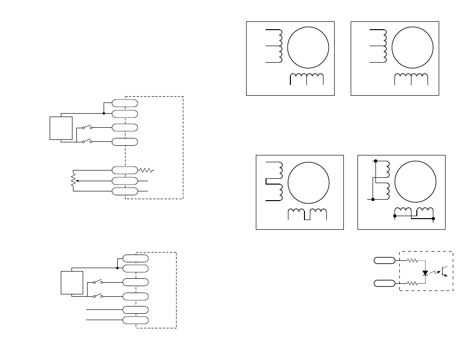
Eight lead motors can also be connected in two ways: series or parallel. As with
six lead motors, series operation gives you more torque at low speeds and less
torque at high speeds. In series operation, the motor should be operated at 30%
less than the rated current to prevent over heating. The wiring diagrams for eight
lead motors are shown below.
A+
A–
NC
B+
B–
NC
6
lead
motor
Red
Black
Red/
Wht
Green
Grn/Wht
White
A+
A–
NC
B+
B–
NC
6
lead
motor
Grn/Wht
White
Green
Red
Red/
Wht
Black
6 Leads Series Connected
6 Leads Center Tap Connected
A+
A–
B+
B–
8
lead
motor
8 Leads Series Connected
8 Leads Parallel Connected
A+
A–
B+
B–
8
lead
motor
Orange
Org/Wht
Blk/Wht
Black
Red
Red/
Wht
Yel/
Wht
Yellow
Orange
Org/
Wht
Blk/Wht
Black
Red
Red/Wht
Yel/
Wht
Yel
low
Connecting Logic
The 2035XD contains optical isolation circuitry to
prevent the electrical noise inherent in switching
amplifiers from interfering with your circuits.
Optical isolation is accomplished by powering the
motor driver from a different supply than your
circuits. There is no electrical connection between
the two: signal communication is achieved by infrared light. When your circuit
turns on or turns off an infrared LED (built into the drive) it signals a logic state to
the phototransistors that are wired to the brains of the drive. A schematic diagram of
the input circuit is shown at the right.
inside 2035XD
Drive Input Circuit
220
Ω
220
Ω
STEP+
STEP-
-10-
Connecting to the Analog Inputs
The analog input of each axis can be used to control the motor speed when that axis
is programmed for oscillator mode. The speed may also be fixed and the analog
input ignored and left unconnected.
+5 volt DC is provided for powering potentiometers. A 1000 to 10000 ohm potenti-
ometer is recommended and should be connected as shown below.
The +5V terminal is an output. Do not connect it to a power supply.
A 0 to 5 volt analog signal may also be used. Usually this signal comes from a
PLC, a PC with data aquisition card or a motion controller. Connections are shown
below.
Connecting an Analog Input to a Potentiometer
1-10k
Ω
pot
cw
ccw
2035XD
DIR+
STEP+
DIR-
STEP-
GND
AIN
+5
+
5 VDC
POWER
SUPPLY
-
direction switch
run/stop switch
(closed=run)
+5 VDC±5%
100
Ω
to ADC
0 VDC
Connecting an Analog Input to an Active Signal
0 - 5V speed signal
signal return
2035XD
DIR+
DIR-
STEP-
GND
AIN
STEP+
+
5 VDC
POWER
SUPPLY
-
direction switch
run/stop switch
(closed=run)