Modes of operation – Applied Motion 3540MO User Manual
Page 6
-15-
-6-
0.4
AMPS/
PHASE
0.1
0.2
0.4
0.8
1.6
0.5
AMPS/
PHASE
0.1
0.2
0.4
0.8
1.6
0.6
AMPS/
PHASE
0.1
0.2
0.4
0.8
1.6
0.7
AMPS/
PHASE
0.1
0.2
0.4
0.8
1.6
0.8
AMPS/
PHASE
0.1
0.2
0.4
0.8
1.6
0.9
AMPS/
PHASE
0.1
0.2
0.4
0.8
1.6
1.0
AMPS/
PHASE
0.1
0.2
0.4
0.8
1.6
1.1
AMPS/
PHASE
0.1
0.2
0.4
0.8
1.6
1.2
AMPS/
PHASE
0.1
0.2
0.4
0.8
1.6
1.3
AMPS/
PHASE
0.1
0.2
0.4
0.8
1.6
1.4
AMPS/
PHASE
0.1
0.2
0.4
0.8
1.6
1.5
AMPS/
PHASE
0.1
0.2
0.4
0.8
1.6
1.6
AMPS/
PHASE
0.1
0.2
0.4
0.8
1.6
1.7
AMPS/
PHASE
0.1
0.2
0.4
0.8
1.6
1.8
AMPS/
PHASE
0.1
0.2
0.4
0.8
1.6
1.9
AMPS/
PHASE
0.1
0.2
0.4
0.8
1.6
2.0
AMPS/
PHASE
0.1
0.2
0.4
0.8
1.6
2.1
AMPS/
PHASE
0.1
0.2
0.4
0.8
1.6
2.2
AMPS/
PHASE
0.1
0.2
0.4
0.8
1.6
2.3
AMPS/
PHASE
0.1
0.2
0.4
0.8
1.6
2.4
AMPS/
PHASE
0.1
0.2
0.4
0.8
1.6
2.5
AMPS/
PHASE
0.1
0.2
0.4
0.8
1.6
2.6
AMPS/
PHASE
0.1
0.2
0.4
0.8
1.6
2.7
AMPS/
PHASE
0.1
0.2
0.4
0.8
1.6
2.8
AMPS/
PHASE
0.1
0.2
0.4
0.8
1.6
2.9
AMPS/
PHASE
0.1
0.2
0.4
0.8
1.6
3.0
AMPS/
PHASE
0.1
0.2
0.4
0.8
1.6
3.1
AMPS/
PHASE
0.1
0.2
0.4
0.8
1.6
3.2
AMPS/
PHASE
0.1
0.2
0.4
0.8
1.6
3.3
AMPS/
PHASE
0.1
0.2
0.4
0.8
1.6
3.4
AMPS/
PHASE
0.1
0.2
0.4
0.8
1.6
3.5
AMPS/
PHASE
0.1
0.2
0.4
0.8
1.6
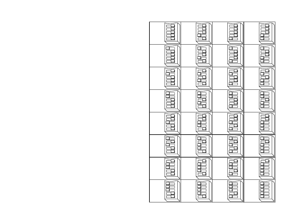
Current Setting Table
45678
45678
45678
45678
45678
45678
45678
45678
45678
45678
45678
45678
45678
45678
45678
45678
45678
45678
45678
45678
45678
45678
45678
45678
45678
45678
45678
45678
45678
45678
45678
45678
Modes of Operation
Note: We refer to an input as being ON when current is flowing
through the input. A signal is OFF when no current is flowing. An
input is OFF when COM and the input terminal are at the same voltage,
or when the input is left unconnected (open).
The 3540 MO features two modes of operation.
• Joystick mode - speed and direction are determined by an external analog
voltage. RUN and DIR inputs can be used for limit switches. SPD (speed) input
selects speed range. LO SPEED and HI SPEED pots adjust the 2 speed ranges.
• Oscillator mode - speed can be controlled by on-board potentiometers and/or
by an external analog voltage. RUN input starts and stops the motor. DIR input
controls direction of rotation. SPD input selects the speed range.
Joystick Mode
In this mode, speed and direction are determined by the voltage applied to the WPR
(wiper) terminal. 2.5 volts is "stopped" (no speed). Increasing the WPR voltage
toward 5 volts results in forward motion: speed increases with voltage. Decreasing
the WPR voltage from 2.5 toward 0 results in reverse motion, with speed increasing
as voltage decreases.
The maximum speed is determined by two things: the state of the SPD input and
the HI SPEED and LO SPEED trimpots. When the SPD input is ON, the speed range
of the joystick can be adjusted with the LO SPEED pot, up to 5 rev/sec (300 rpm)
When the SPD input is OFF (or open), the joystick speed range is adjusted with the
HI SPEED pot, up to 25 rev/sec (1500 rpm). Turning the pots clockwise increases
the speed.
In joystick mode, limit switches can be connected to the 3540 MO to prevent motion
outside of defined limits. The forward limit should be connected to the RUN input
and the reverse limit should be connected to the DIR input. When the forward limit
is ON, the motor will not move forward (that is, when the joystick voltage is between
2.5 and 5 volts.) When the reverse limit is ON, the motor will not move when the
joystick is in the 0 to 2.5 volt range. If you don't need limits, you can leave the RUN
and DIR inputs unconnected.
Joystick mode is set by moving switch #1 toward the word "Joystick". Switch #2
(EXT SPEED) has no effect in Joystick mode.