Connecting a potentiometer to analog input 1, Drive, Analog inputs – Applied Motion ST10-C-CE User Manual
Page 33: Gnd ain +5v out, Ain2
Advertising
33
ST5/10-Si,-Q,-C, IP Hardware manual
920-0004 Rev. F
6/10/14
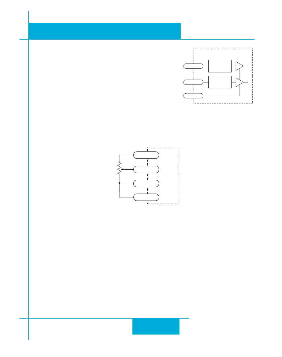
Connecting a Potentiometer to Analog Input 1
Analog Inputs
The ST drives feature two analog inputs. Each input can accept
a signal range of 0 to 5 VDC, ±5 VDC, 0 to 10 VDC or ±10 VDC.
The drive can be configured to operate at a speed or position
that is proportional to the analog signal.
A shielded cable is recommended for electrically noisy
environments.
Use the ST Configurator software to set the signal range, offset,
deadband and filter frequency.
inside drive
AIN1
AIN2
GND
1
2
13
DB-25 Connector
Signal
Conditioning
Signal
Conditioning
1-10kW
pot
cw
ccw
DRIVE
GND
AIN
+5V OUT
18
1
13
AIN2
2
Advertising
This manual is related to the following products: