Applied Motion ST10-Si-NE User Manual
St5/10-si quick setup guide, Requirements, Step 1
Serial No
Error Codes
GR-Green RD-RED
POSITION LIMIT
1 GR + 1 RD
CCW LIMIT TRIP
1 GR + 2 RD
CW LIMIT TRIP
2 GR + 2 RD
DRIVE OVER TEMP
1 GR + 3 RD
MOTOR OVER TEMP
2 GR + 3 RD
VO
LTAGE HIGH
1 GR + 4 RD
VO
LTAGE LOW
2 GR + 4 RD
OVER CURRENT
1 GR + 5 RD
HALL
FAIL
1 GR + 6 RD
ENCODER
FAIL
2 GR + 6 RD
COMM ERRO
R
1 GR + 7 RD
Fro
nt V
iew
X CO
MM
ON
X7 /
CW
Lim
it
X3
/ Se
rvo
Ena
ble
X5
X4 /
Ala
rm
Res
et
Ana
log
IN-
Ana
log
IN+
X2
/ DI
R-
X2 /
DIR
+
X1 /
STE
P / P
WM
+
X1
/ ST
EP /
PW
M-
GN
D
GN
D
A+
A-
B+
B-
Z+
Z-
+5V
OU
T
Y CO
MM
ON
Y3 /
ALA
RM
Y2 /
INP
OSN
Y1 /
BRA
KE
18
17
16
15
14
13
12
11
10
9
8
7
6
5
4
2 3
1
1920
2122
2324
25
r
e
d
o
c
n
E
st
u
p
t
u
O
X6 /
CCW
Lim
it
IN/OUT 1
ST5-Q
ST5/10-Si Quick Setup Guide
Requirements
▪
A compatible stepper motor.
▪
A small flat blade screwdriver for tightening the connectors (included).
▪
A personal computer running Microsoft Windows 95, 98, NT, Me, 2000, XP, Vista or 7.
▪
Si Programmer™ software, available at: http://www.applied-motion.com
▪
An Applied Motion programming cable (included).
▪
For more detailed information, please download and read the ST5/10-QSiC Hard-
ware Manual, available at www.applied-motion.com/support/manuals.
To begin, make sure you have the following equipment:
Step 1
a)
Download and install the Si Programmer™ software.
b)
Launch the software by clicking:
Start / Programs / Applied Motion Products / Si Programmer
c)
Connect the drive to your PC using the appropriate programming cable.
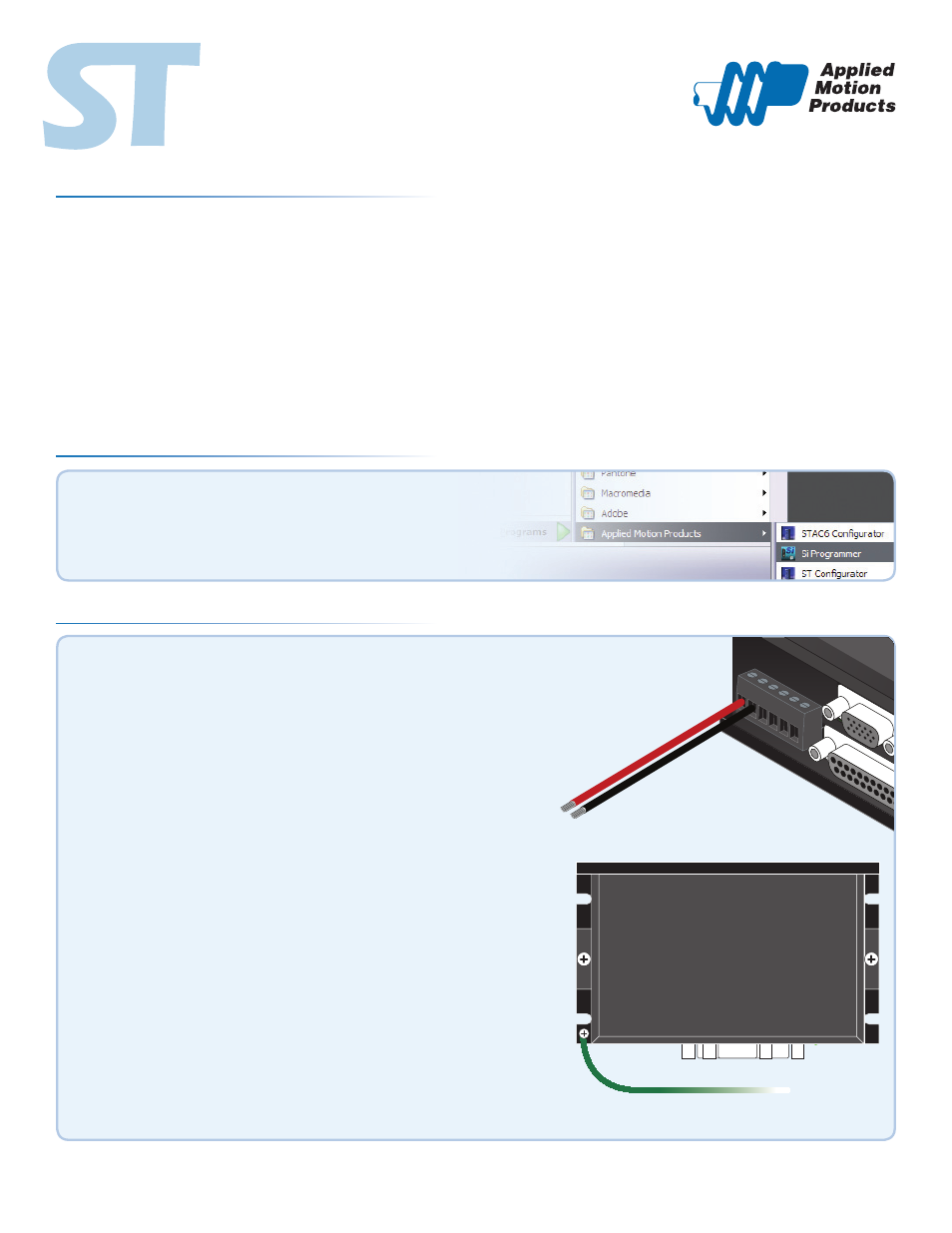
Step 2
Warning - If you are using a non-Applied Motion motor, do not connect the mo-
tor until after you have configured the drive for your motor. Refer to Step 5.
a)
Wire the drive to the DC power source.
(do not apply power until all connections to the drive have been made)
Note, the ST5-Si accepts DC voltages from 24-48V,
while the ST10-Si accepts DC voltages from 24-80V.
b)
Ensure a proper earth ground connection by using the screw on the left
side of the chassis.
If using an external fuse, we recommend the following:
ST5-Si
: 3AG, 4 amp (Littlefuse 313004P)
ST10-Si
: 3AG, 6.25 amp (Littlefuse 3136.25P)
See the ST5/10-QSiC Hardware Manual for more information about
power supply and fuse selection.
Connection Panel
920-0008 C