Applied Motion STAC6-C User Manual
Stac6-c quick setup guide, Requirements, Step 1 - wiring
STAC6-C Quick Setup Guide
Requirements
A small flat blade screwdriver for tightening the connectors (included).
▪
A personal computer running Microsoft Windows 98, 2000, ME, NT, XP, Vista or 7.
▪
▪
An RS-232 Applied Motion programming cable (included)
▪
4 pin spring connector (included) for connecting to the CAN network.
▪
A compatible stepper motor
▪
For more detailed information, please do
▪
To begin, make sure you have the following equipment:
Step 1 - Wiring
920-0042 A
920-0046 A
STAC6-C Quick Setup Guide
Wire the drive to the AC power source.
▪
(Do not apply power until Step 3)
Note: The STAC6-C uses 120VAC single-phase power.
The STAC6-C-220 uses 220VAC single-phase power.
If using an external fuse, we recommend the follow-
ing:
STAC6-C
: 6 amp fast acting
STAC6-C-220
: 3 amp fast acting
See the hardware manual for more information
about connecting AC power.
Ensure a proper earth ground connection.
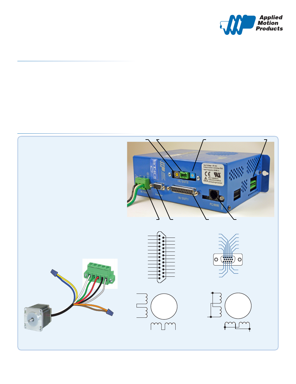
Node ID
CANOpen Connector
Bit Rate
Motor Connector
Power Connection
Encoder Connector
I/O Connector
RS232 Connector
Connect the drive to the motor.
▪
Refer to the wiring diagrams below. For details and rec-
ommended motors, see the .
Connect the I/O
▪
Connect the Encoder
▪
whit
e
gr
een
red
black
shield
brown
orange
yello
w
blue
A+ A- B+ B- FG
X COMMON
X3 / Enable
X5 / CW JOG
X4 / Alarm Reset
Analog IN
Analog IN
X2 / DIR -
X2 / DIR +
X1 / STEP+
X1 / STEP -
GND
GND
X8/CCW LIMIT -
X8/CCW LIMIT+
X7/CW LIMIT -
X7/CW LIMIT+
Y4 -
Y4+
+5V OUT
Y COMMON
Y3 / FAULT
Y2 / MOTION
Y1 / BRAKE
18
17
16
15
14
13
12
11
10
9
8
7
6
5
4
2
3
1
19
20
21
22
23
24
25
X6 / CCW JOG
IN/OUT - ST5/10 - Q/Si
Z+ (5)
NC (10)
B- (4)
NC (9)
B+ (3)
NC (13)
NC (14)
NC (15)
(12) NC
(11) NC
(6) Z-
(1) A+
(7) +5VDC 200mA
(2) A-
(8) GND
PC GND
PC TX-/RX- or B
PC TX+/RX+ or A
+RX- +TX- GND
Drive 1
Drive 2
Drive 3
+RX- +TX- GND +RX- +TX- GND
PC GND
PC RX-
PC RX+
PC TX-
PC TX+
+RX- +TX- GND
Drive 1
Drive 2
Drive 3
+RX- +TX- GND +RX- +TX- GND
Front View
X COMMON
X7 / CW Limit
X3 / Enable
X5
X4 / Alarm Reset
Analog IN-
Analog IN+
X2 / DIR-
X2 / DIR+
X1 / STEP +
X1 / STEP -
GND
GND
+5V OUT
Y COMMON
Y3 / FAULT
Y2 / MOTION
Y1 / BRAKE
1 8
1 7
1 6
1 5
1 4
1 3
1 2
1 1
1 0
9
8
7
6
5
4
2
3
1
1 9
2 0
2 1
2 2
2 3
2 4
2 5
X6 / CCW Limit
IN/OUT 1
+5V OUT
+12V OUT
GND
GND
ENCODER
*Optional
A+
A–
B+
B–
8
lead
motor
Series Connected
8 Leads Parallel Connected
A+
A–
B+
B–
8
lead
motor
White
Orange
Brown
Green
Red
Yellow
Blue
Black
Orange
Red
Brown
Yellow
Blue
Black
White
Green
Motor Connector