Applied Motion STM23C-3CE User Manual
Stm23c/24c quick setup guide, Requirements, Step 1 - wiring
STM23C/24C Quick Setup Guide
Requirements
A small flat blade screwdriver for tightening the connectors (included).
▪
A personal computer running Microsoft Windows 98, 2000, ME, NT, XP, Vista or 7.
▪
ST Configurator™
▪
software (available at www.applied-motion.com).
3 pin spring connector (included) for connecting to the CAN network.
▪
For more detailed information, please download and read the
▪
STM23 Hardware Manual or STM24
Hardware Manual, available at www.applied-motion.com/support/manuals.
To begin, make sure you have the following equipment:
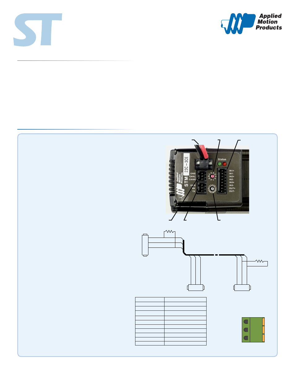
Step 1 - Wiring
Wire the drive to the DC power source.
▪
Do not apply power until Step 3.
Note - the STM23C and STM24C accepts DC voltages from
12-70V. If using an external fuse, we recommend: STM23:
4 amp fast acting, STM24C: 5 amp fast acting.
See the STM23 or STM24 Hardware Manuals for more infor-
mation about power supply and fuse selection.
Connect I/O, if required by your application.
▪
Connect to CAN network.
▪
Applied Motion Products STM23C and STM24C drives
use a three-pin spring connector, that conforms to the
DR303 specification. The connector should be wired in a
daisy-chain configuration with a 120 Ohm resistor used to
terminate each end.
Set BitRate, Node ID
▪
CANOpen Bitrate - AMP CANOpen drives have three set-
tings, one for Bit Rate and two for Node ID. The Bit Rate is
configured using a ten-position switch. See Bit Rate table
for the Bit Rate settings.
The Node ID is configured using a sixteen position switch to
set up the lower four bits of the Node ID. The upper three
bits of the Node ID are set using the ST Configurator™. Valid
ranges for the Node ID are 0x01 through 0x7F. Node ID
0x00 is reserved in accordance to DS301 specification.
Note: The Node ID and Bit Rate is captured only after a
power cycle, or after a network reset command has been
sent. Changing the switches while the drive is powered on
will NOT change the Node ID until one of these conditions
has also been met.
Connect the RS-232 programming cable.
▪
920-0043 B
POWER CONNECTIONS
BIT RATE
I/O CONNECTIONS
NODE ID
CANOpen
RS232
CAN_H
CAN_L
GND
CAN_BUS
2
3
7
DSUB9
Female
CAN_L
GND
CAN_H
R Termination
120 Ohm nominal
CAN_L
GND
CAN_H
3
2
1
.1 Spacing
Spring Plug
R Termination
120 Ohm nominal
CAN_L
GND
CAN_H
3
2
1
.1 Spacing
Spring Plug
Switch Setting
Resultant Bit Rate
0
1 Mbps
1
800kbps
2
500 kbps
3
250 kbps
4
125 kbps
5
50 kbps
6
20 kbps
7
12.5 kbps
8
n/a
9
n/a
Bit Rate Table
3 Pin Connector