Atlona AT HD V214 User Manual
Page 4
3
www.atlona.com
Toll free: 1-877-536-3976
Local: 1-408-962-0515
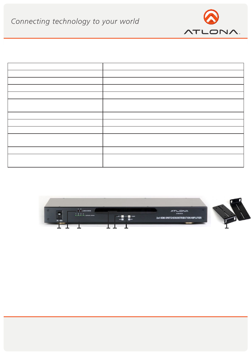
1. Front Panel
1. POWER ON SWITCH. The power switch turns the unit on and off. The LED will illuminate red to indicate
that the switcher is ON and is receiving power
2. INPUT SOURCES STATUS DISPLAY. 2 Input sources 1 to 2 LED illuminate blue to indicate that a video
source is present on that input.
3. OUTPUT SOURCES STATUS DISPLAY. Output Channel 1 though 4 show on LED display.
4. OUTPUT CHANNEL DISPLAY. A separate output-1 and 2 source channel select displays are provided for
each destination. Select sources are 1-HDMI or 2-HDMI
5. SOURCES SELECT BUTTONS. A separate input 1 and 2 source select buttons are provided for each des-
tination.
6. IR SENSOR. The IR sensor receives IR commands from the supplied remote control.
7. 9 INCH Rack Ears. 19 inch Rack Ears (pair)
Type of Switcher
2 HDMI inputs to 4 HDMI outputs
Input Signals
Video (TMDS) 0.5~1.0Vpp, DDC 5Vpp
Signal Supports
HDMI and DVI (with hdmi to dvi adapter)
Supported Resolutions
1920x1200 or 1080p
Audio Supported
DTS-HD Master Audio, Dolby True -HD & Dolby Digital Plus
Video Supported
RGB/YCBCR: 24/30/36-bits
YCBCR: 8/10/12/16/20/24-bits
Double data rate interface for RGB/YCBCR 12/15/18-bits
Controls
IR, buttons selection on the front panel & RS232
Data Rates
250Mbps to 6.75Gbps
IR Extender Distance
up to 1000ft, allows users to control the switch from as far as
1000ft away
Safety Approvals
CE, FCC and RoHs
Power Supply
DC12V (consumption 400mA Max) (Universal 50/60Hz,
100/230V)
SPECIFICATIONS
PANEL DESCRIPTION
1
3
6
2
4 5
7