Dipswitch installation – Atlona AT VGA RS300SRS V2 User Manual
Page 9
7
Toll free: 1-877-536-3976
Local: 1-408-962-0515
atlona.com
9
O
O
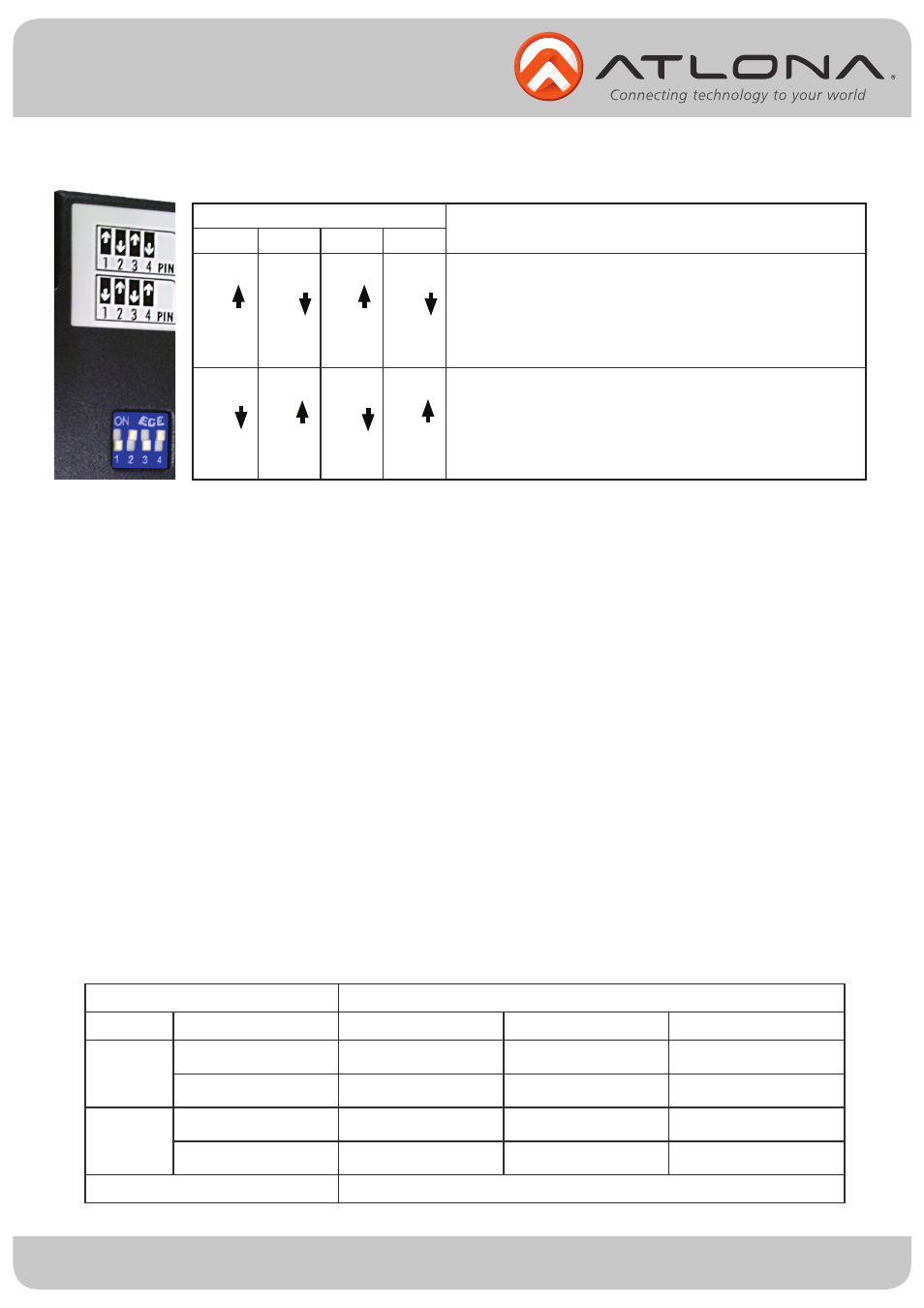
DIP
Pin-1
P
ON [ ]
OF
FF [ ]
O
Note:
1. Connect VGA source, audio source, and RS-232 devices to the AT-VGA-RS300S (Sender)
2. Connect VGA display, audio, and RS-232 devices to the AT-VGA-RS300R (Receiver)
3. Connect a CAT5/5e/6 cable between the transmitting and receiving units.
4. Plug in 5V DC power supply unit to the power jack of the AT-VGA-RS300R (Receiver)
5. Plug in 5V DC power supply unit to the power jack of the AT-VGA-RS300S (Sender)
6. Adjust GAIN control to an appropriate level for a range of input signals (brightness).
7. EQ Control is to equalize the wave form of the receiving video signal (sharpenss).
P Switch Position
P in-2
P
F F [ ]
ON
N [ ]
OF
1. TxD: The 3rd pin of RS-232, which is in charge of sending data
2. RxD: The 2nd pin of RS-232, which is in charge of receiving data
3. The Dip Switch is located on the bottom of the AT-VGA-RS300S (sender)
in-3
Pi n
N [ ]
OF F
F [ ]
ON
n-4
F [ ]
Sender & Receiver Extender Mode -
TxD
1
RxD
2
[ ]
Master to Slave Mode -
TxD
RxD
2
A
of AT-VGA-RS300S is connected to TxD of AT-VGA-RS300R
of AT-VGA-RS300S is connected to TxD of AT-VGA-RS300R
A
of AT-VGA-RS300S is connected to RxD of AT-VGA-RS300R
A
of AT-VGA-RS300S is connected to RxD of AT-VGA-RS300R
Description
Dipswitch
Installation
Performance Guide for VGA Transmissions over CAT5/5e/6 Cable
Performance rating
Wiring
Solid
Stranded
Shielding
Unshielded (UTP)
Shielded (STP)
Unshielded (UTP)
Shielded (STP)
Termination
C A
*
*
Please use EIA/TIA-568-B termination (T568B) at all times
AT5
***
***
*
*
Type of CAT5/5e/6 Cable
C A
**
*
*
AT5e
***
***
**
*
C A
**
**
*
*
AT6
****
***
**
**