Casella CEL CEL-490 User Manual
Print on a3
Preparation
DO NOT attempt to power from an external source
without first consulting Section 1.8 of the handbook.
Install 4 x AA size batteries in the compartment in the
underside of the unit.
Screw the Class 1 microphone finger-tight on to the
preamplifier.
Connect the Class 1 preamplifier plus microphone or the
Class 2 microphone/preamplifier assembly by inserting it
into the socket in the top of the instrument case with
the red dot facing the front to ensure correct pin location.
Menus & Control
All operations are based upon a series of menus
arranged as shown in the figure.
A combination of function and navigator keys on the
front panel are used to move around the menu system
and implement commands. The functions are as follows.
Power ON/OFF.
and
Navigator keys that move the highlight around the
options.
and
Navigator keys that change the contents of a field.
Enable/Disable Quick Edit.
Display Main menu (may require several presses).
Accesses data screens.
On screen show active keys.
Shows that Quick Edit mode is available.
Menu options are implemented in two ways.
1.
Leave the required option highlighted.
2.
Use the quick edit function to change the option.
(Press
to activate and deactivate the function).
Configuring the Instrument
The instrument configuration specifies how the
instrument communicates with the operator and via the
RS232 interface.
Press
to switch the instrument ON and obtain the
Calibration Check screen.
Press
to see the Main menu which gives access to
further menus that select Measurement Mode, Setup,
Calibration, Data Recall from Memory and Configuration.
An indication such as 2/6 at the bottom of a screen
shows that the second of six possible options is
highlighted.
Press
to move to Configure.
Press
to see the configuration menu.
Make choices about the RS232 Communication Baud
rate, Menu Language, Backlight operation and
Microphone Response (Free Field or Random) as
appropriate by leaving the required choice highlighted on
the screen.
The instrument Time and Date, Graph Range and AC
Output for recording can also be set from the
Configuration menu.
Press
(several times) to return to the Main menu.
Calibration
Calibration ensures that the instrument is measuring
noise accurately. The Calibration menu is displayed at
the end of the self test sequence.
If Scale is mentioned, move to the Main menu, select
Calibration, then press
to see the Calibration menu.
Insert the 1/2" microphone far enough into the calibrator
cavity to be in contact with the stop in its cavity.
Insert the 1/4" microphone far enough into the coupler
cavity to be in contact with the stop in its cavity and the
microphone plus coupler far enough into the calibrator
cavity to be in contact with the stop in its cavity.
Support the calibrator and sound level meter so that the
microphone points vertically upwards to avoid distorting
the calibration volume.
Switch the calibrator ON.
When an incorrect level is shown, press
to set the
display to indicate 114.0 dB automatically and YES to
save the calibration.
If the microphone and response set (Free Field/Random)
require that some other value should be set, perform a
manual calibration. Use
and
to select Auto, press
to select Last Cal, now use
and
to adjust the
display to the correct value. Press
to save the
calibration.
Select Mode
The Measure Mode specifies the Bandwidth to be used
for measurement.
In the Main menu, move to Measure Mode and press
to see the Measure Mode menu.
Select a bandwidth for use by highlighting it.
Alternatively, use the Setup option (below) to select a
pre-stored setup for use.
Press
to return to the Main menu.
Select Setup
The Setup specifies the particular parameters that are to
be measured.
In the Main menu, move to Setup and press
to see
the Setup menu.
Select a pre-saved setup for use by highlighting it.
When a setup is to be prepared and saved, press
to
move to a setup options menu. This allows the following
measurement parameters to be specified.
Broadband parameters:
SLM Response:
RMS-, time- and peak-weightings, plus
energy exchange rate Q.
Period Results:
Interval between measurements,
Profiles for up to 15 broadband parameters.
The maximum Run Time for the selected
combination will be shown
Measured Functions:
Up to 15 Broadband Period parameters,
Up to 14 Broadband Cumulative parameters.
Dose Results:
Threshold, for including values in calculation
Normalisation period, to allow results from
different durations to be compared.
Narrowband parameters (when available):
SLM Response:
RMS-, time- and peak-weightings, plus
energy exchange rate Q.
Period Results (CEL-490 only):
Interval between measurements,
Note that no profiles are available for narrowband
measurement.
Measured Functions:
Up to 10 Narrowband Period parameters,
Up to 9 Narrowband Cumulative parameters.
Set Timers
From the Main menu, select Timers, to see a Timers
menu that gives the option of switching the Timers Off,
setting a Duration Timer, or setting a Delay only on a
CEL-490.
Make choices as appropriate by leaving them high-
lighted on the screen.
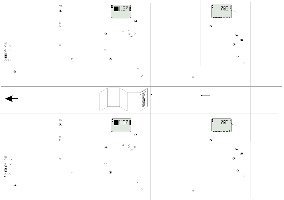
Broadband Measurement
When broadband measurement is selected, press
several times from any Menu screen until a broadband
measurement screen is displayed. Broadband screens
show one principal and four secondary parameters that
can all be changed by means of the Quick Edit function.
Press
to start a measurement run and store results.
If a clock is shown, a timed measurement has been set,
refer to Section 3.1 of the Handbook.
Only data stored during the current run can be reviewed
while more data is being collected. Press
then use
the navigator keys to review data screens.
When sufficient data has been inspected, press
to
return to the measurement screen.
When the run is to be stopped, press
and see the
following options:
Stop run (and store data),
Restart run (abandon the current run and start a
new run),
Continue run (continue the interrupted run).
Select an option and confirm it by pressing
.
Narrowband Measurement
When narrowband measurement is selected, press
several times from any Menu screen until a narrowband
measurement screen is displayed.
Narrowband screens show a single identified parameter
with a 140 dB measurement range.
The RMS weighting for the first broadband column is
the weighting used for all narrowband columns.
Preparation
DO NOT attempt to power from an external source
without first consulting Section 1.8 of the handbook.
Install 4 x AA size batteries in the compartment in the
underside of the unit.
Screw the Class 1 microphone finger-tight on to the
preamplifier.
Connect the Class 1 preamplifier plus microphone or the
Class 2 microphone/preamplifier assembly by inserting it
into the socket in the top of the instrument case with
the red dot facing the front to ensure correct pin location.
Menus & Control
All operations are based upon a series of menus
arranged as shown in the figure.
A combination of function and navigator keys on the
front panel are used to move around the menu system
and implement commands. The functions are as follows.
Power ON/OFF.
and
Navigator keys that move the highlight around the
options.
and
Navigator keys that change the contents of a field.
Enable/Disable Quick Edit.
Display Main menu (may require several presses).
Accesses data screens.
On screen show active keys.
Shows that Quick Edit mode is available.
Menu options are implemented in two ways.
1.
Leave the required option highlighted.
2.
Use the quick edit function to change the option.
(Press
to activate and deactivate the function).
Configuring the Instrument
The instrument configuration specifies how the
instrument communicates with the operator and via the
RS232 interface.
Press
to switch the instrument ON and obtain the
Calibration Check screen.
Press
to see the Main menu which gives access to
further menus that select Measurement Mode, Setup,
Calibration, Data Recall from Memory and Configuration.
An indication such as 2/6 at the bottom of a screen
shows that the second of six possible options is
highlighted.
Press
to move to Configure.
Press
to see the configuration menu.
Make choices about the RS232 Communication Baud
rate, Menu Language, Backlight operation and
Microphone Response (Free Field or Random) as
appropriate by leaving the required choice highlighted on
the screen.
The instrument Time and Date, Graph Range and AC
Output for recording can also be set from the
Configuration menu.
Press
(several times) to return to the Main menu.
Calibration
Calibration ensures that the instrument is measuring
noise accurately. The Calibration menu is displayed at
the end of the self test sequence.
If Scale is mentioned, move to the Main menu, select
Calibration, then press
to see the Calibration menu.
Insert the 1/2" microphone far enough into the calibrator
cavity to be in contact with the stop in its cavity.
Insert the 1/4" microphone far enough into the coupler
cavity to be in contact with the stop in its cavity and the
microphone plus coupler far enough into the calibrator
cavity to be in contact with the stop in its cavity.
Support the calibrator and sound level meter so that the
microphone points vertically upwards to avoid distorting
the calibration volume.
Switch the calibrator ON.
When an incorrect level is shown, press
to set the
display to indicate 114.0 dB automatically and YES to
save the calibration.
If the microphone and response set (Free Field/Random)
require that some other value should be set, perform a
manual calibration. Use
and
to select Auto, press
to select Last Cal, now use
and
to adjust the
display to the correct value. Press
to save the
calibration.
Select Mode
The Measure Mode specifies the Bandwidth to be used
for measurement.
In the Main menu, move to Measure Mode and press
to see the Measure Mode menu.
Select a bandwidth for use by highlighting it.
Alternatively, use the Setup option (below) to select a
pre-stored setup for use.
Press
to return to the Main menu.
Select Setup
The Setup specifies the particular parameters that are to
be measured.
In the Main menu, move to Setup and press
to see
the Setup menu.
Select a pre-saved setup for use by highlighting it.
When a setup is to be prepared and saved, press
to
move to a setup options menu. This allows the following
measurement parameters to be specified.
Broadband parameters:
SLM Response:
RMS-, time- and peak-weightings, plus
energy exchange rate Q.
Period Results:
Interval between measurements,
Profiles for up to 15 broadband parameters.
The maximum Run Time for the selected
combination will be shown
Measured Functions:
Up to 15 Broadband Period parameters,
Up to 14 Broadband Cumulative parameters.
Dose Results:
Threshold, for including values in calculation
Normalisation period, to allow results from
different durations to be compared.
Narrowband parameters (when available):
SLM Response:
RMS-, time- and peak-weightings, plus
energy exchange rate Q.
Period Results (CEL-490 only):
Interval between measurements,
Note that no profiles are available for narrowband
measurement.
Measured Functions:
Up to 10 Narrowband Period parameters,
Up to 9 Narrowband Cumulative parameters.
Set Timers
From the Main menu, select Timers, to see a Timers
menu that gives the option of switching the Timers Off,
setting a Duration Timer, or setting a Delay only on a
CEL-490.
Make choices as appropriate by leaving them high-
lighted on the screen.
Broadband Measurement
When broadband measurement is selected, press
several times from any Menu screen until a broadband
measurement screen is displayed. Broadband screens
show one principal and four secondary parameters that
can all be changed by means of the Quick Edit function.
Press
to start a measurement run and store results.
If a clock is shown, a timed measurement has been set,
refer to Section 3.1 of the Handbook.
Only data stored during the current run can be reviewed
while more data is being collected. Press
then use
the navigator keys to review data screens.
When sufficient data has been inspected, press
to
return to the measurement screen.
When the run is to be stopped, press
and see the
following options:
Stop run (and store data),
Restart run (abandon the current run and start a
new run),
Continue run (continue the interrupted run).
Select an option and confirm it by pressing
.
Narrowband Measurement
When narrowband measurement is selected, press
several times from any Menu screen until a narrowband
measurement screen is displayed.
Narrowband screens show a single identified parameter
with a 140 dB measurement range.
The RMS weighting for the first broadband column is
the weighting used for all narrowband columns.
dB
114.Ø dB
Auto
L
ZF
v04013
Ø9JanØ4 11:28
dB
114.Ø dB
Auto
L
ZF
v04013
Ø9JanØ4 11:28
AFmx
dB
AF
Aeq
AFmn
Zpk
L
L
L
L
L
v04012
0
140
AFmx
dB
AF
Aeq
AFmn
Zpk
L
L
L
L
L
v04012
0
140
Quick Edit is
available
Quick Edit is
available
Print on A3
Fold as Shown
Fold Line
Fold Line
TOP
Cut Here
v04003
Class
2, 1/4"
Microphone
&
Preamplifier
Pull the
knurled
sleeve
outwards
to
release
the
connector
ON/OFF
Navigator
keys
Sta
rt/
Pause
/
Resta
rt
Access
data
Change
menu
Ena
ble
Quick
edit/
Select
Back
light
Sto
p
(needs
to confirm)
Protective
grill ( )
Class
1, 1/2"
Microphone
Preamplifier
Red
dot
do
not
remove
FIELD
GUIDE
to
CEL-450/490
Sound
Level
Meters
Th
e C
EL-450
and
CEL-490
Sound
Level Meters consi
st
of the
instr
ument
unit
preamplifier
and
microphone
show
n.