Casella CEL CEL-360 User Manual
Casella CEL Measuring instruments
Introduction
The instruments in the CEL-320/360 Series consist of the instrument unit shown,
plus CEL-6681 Dosimeter Microphone and Cable, or CEL-425 Microphone Adaptor.
Display
Preparation
Connect a 9 V battery (6LF22) to the terminals in the battery compartment in the
rear of the instrument.
DO NOT disconnect the battery once runs have been stored;
they will be lost.
With the instrument switched OFF, insert the cable connector of the Dosimeter
Microphone or the Microphone Adaptor into the socket in the top end of the case with
the red dot facing the front of the dosimeter.
Operation of the instrument is achieved by a simple sequence of key strokes.
Field Accuracy Check
Use a CEL-282 (Class 2) or CEL-284/2 (Class 1) Calibrator to perform a field
accuracy check (acoustic calibration) each time the instrument is switched ON and
again at the end of measurement.
Fit the CEL-4725 Coupler (supplied with the calibrator) into the calibrator cavity,
making sure it is firmly in contact with the shoulder in the cavity.
Fit the microphone into the coupler cavity, again making sure it makes contact
with the shoulder in the in the cavity.
Switch the calibrator ON and proceed as follows.
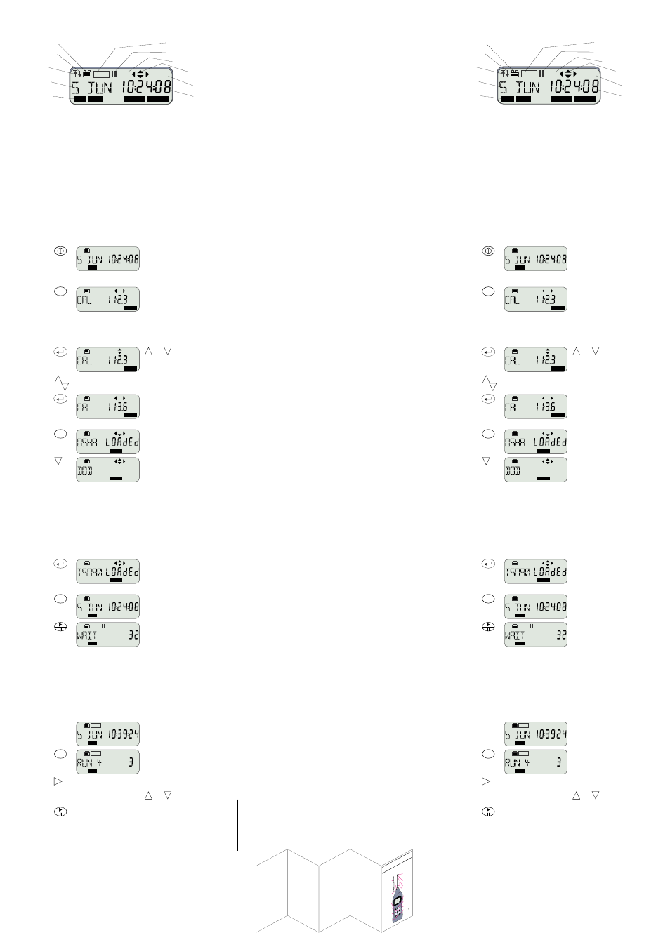
Operation
Press
Display Shows
Comments
1. Switch
instrument
ON
Start Up messages showing
Instrument Type,
Serial number (if set),
Print (only when the print cable is
connected in place of a microphone),
Firmware Version,
finishing with last used
Operating Mode.
2. Change
Mode
re-
peatedly
Select Option to allow Acoustic
Calibration.
The display shows the current SPL.
3. Enable
Level
Change
and
are now enabled.
The display shows the current SPL.
4. Change
Indicated
Level
(or
)
Indicated level rises (falls) 0.05 dB for each key press.
Adjust to correct level for CEL-320/360 microphones at standard
temperature and pressure =
113.6 dB
.
5. Set (Accept)
Calibration
Level
The 113.6 dB calibration level is now
set, and will be stored by the
microphone assembly.
Select Dose Measurement Set Up
1. Change
Operating
Mode
sufficient
times
The first display always shows the
currently loaded set up: for example
OSHA dose measurement.
2. Select
another
Setup
several
times
Select a set up from:
OSHA procedures Q = 5, Crit 90 dB,
A-wtd levels >80 dB and >90 dB,
MSHA procedures Q = 5, Crit 90 dB,
A-wtd levels >80 dB and >90 dB,
DOD procedures Q = 4,
For further information on set
ups, consult the User Manual.
Crit 85 dB, A-wtd levels >80 dB,
ACGIH procedures Q = 3,
Crit 85 dB, A-wtd levels >80 dB,
ISO85 procedures Q = 3,
Crit 85 dB, A-wtd levels >70 dB,
ISO90 procedures Q = 3,
Crit 90 dB, A-wtd levels >70 dB,
special procedure for logging noise
data as SLM.
3. Load
Selected
Setup for
use
A Loaded message shows that the
selected Setup is now active: for
example ISO procedure with 90 dB
Criterion.
Measure and Store Dose Data
1. Change
Operating
Mode
Sufficient
times
Dose Measurement.
Dose data will be saved in the next
available data store.
2. Start Run
(Store Data)
When the run timer of a CEL-360 is
ON with beginning and End Times set,
the instrument waits counting back
the time remaining until the run starts.
When the run timer of a CEL-360 is
ON with Sync on, the instrument
waits until the clock is synchronised
with any selected profile time before
the run starts.
With a CEL-320 or when the run timer
of a CEL-360 is OFF, the instrument
waits for the next whole clock second,
then starts the run.
3. Then
The REC icon indicates that the
instrument is now storing data in the
first available store.
4. Inspect
data from
the
Current Run
The display shows where data from
the current run is being saved (store
4), and on a CEL-360 indicates the
number of completed profile periods
(3).
5. Inspect
further data
from the
Current Run
sufficient
times
Data from Current Run.
Displays will be updated
while the run is in progress.
The display cycles through data from
the current run.
Some of the display screens offer
and
options that show
further parameters.
6. If Required
Pause the run (II icon).
Press again to resume the run.
DATA
MENU
OPTION
OPTION
OPTION
MENU
SET UP
A
SET UP
A
SET UP
A
MENU
DATA
DATA
DATA
REC
DATA
REC
DATA
dB%
REC
Current Mode,
Pressing the MENU
key will select each
of these in turn
Current Data
or Time
Current Units
Measurement is Paused
Frequency Weighting
Indicates Active
Option Keys
SLM DATA
SET UP OPTION
CA
01043
Measurement
Identity or Date
Battery Condition
Data is Being Recorded
Overload has
Occurred
Under range has
Occurred
Introduction
The instruments in the CEL-320/360 Series consist of the instrument unit shown,
plus CEL-6681 Dosimeter Microphone and Cable, or CEL-425 Microphone Adaptor.
Display
Preparation
Connect a 9 V battery (6LF22) to the terminals in the battery compartment in the
rear of the instrument.
DO NOT disconnect the battery once runs have been stored;
they will be lost.
With the instrument switched OFF, insert the cable connector of the Dosimeter
Microphone or the Microphone Adaptor into the socket in the top end of the case with
the red dot facing the front of the dosimeter.
Operation of the instrument is achieved by a simple sequence of key strokes.
Field Accuracy Check
Use a CEL-282 (Class 2) or CEL-284/2 (Class 1) Calibrator to perform a field
accuracy check (acoustic calibration) each time the instrument is switched ON and
again at the end of measurement.
Fit the CEL-4725 Coupler (supplied with the calibrator) into the calibrator cavity,
making sure it is firmly in contact with the shoulder in the cavity.
Fit the microphone into the coupler cavity, again making sure it makes contact
with the shoulder in the in the cavity.
Switch the calibrator ON and proceed as follows.
Operation
Press
Display Shows
Comments
1. Switch
instrument
ON
Start Up messages showing
Instrument Type,
Serial number (if set),
Print (only when the print cable is
connected in place of a microphone),
Firmware Version,
finishing with last used
Operating Mode.
2. Change
Mode
re-
peatedly
Select Option to allow Acoustic
Calibration.
The display shows the current SPL.
3. Enable
Level
Change
and
are now enabled.
The display shows the current SPL.
4. Change
Indicated
Level
(or
)
Indicated level rises (falls) 0.05 dB for each key press.
Adjust to correct level for CEL-420/460 microphones at standard
temperature and pressure =
113.6 dB
.
5. Set (Accept)
Calibration
Level
The 113.6 dB calibration level is now
set, and will be stored by the
microphone assembly.
Select Dose Measurement Set Up
1. Change
Operating
Mode
sufficient
times
The first display always shows the
currently loaded set up: for example
OSHA dose measurement.
2. Select
another
Setup
several
times
Select a set up from:
OSHA procedures Q = 5, Crit 90 dB,
A-wtd levels >80 dB and >90 dB,
MSHA procedures Q = 5, Crit 90 dB,
A-wtd levels >80 dB and >90 dB,
DOD procedures Q = 4,
For further information on set
ups, consult the User Manual.
Crit 85 dB, A-wtd levels >80 dB,
NIOSH procedures Q = 3,
Crit 85 dB, A-wtd levels >80 dB,
ISO85 procedures Q = 3,
Crit 85 dB, A-wtd levels >70 dB,
ISO90 procedures Q = 3,
Crit 90 dB, A-wtd levels >70 dB,
Meter special procedure for logging
noise data as SLM.
3. Load
Selected
Setup for
use
A Loaded message shows that the
selected Setup is now active - for
example ISO procedure with 90 dB
Criterion.
Measure Dose
1. Change
Operating
Mode
Sufficient
times
Dose Measurement.
Dose data will be saved in the next
available data store.
2. Start Run
(Store Data)
When the run timer of a CEL-360 is
ON with beginning and End Times set,
the instrument waits counting back
the time remaining until the run starts.
When the run timer of a CEL-360 is
ON with Sync on, the instrument
waits until the clock is synchronised
with any selected profile interval
before the run starts.
With a CEL-320 or when the run timer
of a CEL-360 is OFF, the instrument
waits for the next whole clock second,
then starts the run.
3. Then
The REC icon indicates that the
instrument is now storing data in the
first available store.
4. Inspect
data from
the
Current Run
The display shows where data from
the current run is being saved (store
4), and on a CEL-360 indicates the
number of completed profile periods
(3).
5. Inspect
further data
from the
Current Run
sufficient
times
Data from Current Run.
Displays will be updated
while the run is in progress.
The display cycles through data from
the current run.
Some of the display screens offer
and
options that show
further parameters.
6. If Required
Pause the run (II icon).
Press again to resume the run.
DATA
MENU
OPTION
OPTION
OPTION
MENU
SET UP
A
SET UP
A
SET UP
A
MENU
DATA
DATA
DATA
REC
DATA
REC
DATA
MENU
DA
TA
01009
Type
2,
1/4"
Microphone
&
Preamplifier
Pull
the
knurled
sleeve
outwards
to
release
the
connector
ON/OFF
Navigator
key
s
Start/
Pause/
Restart
Access
data
Change
menu
Enables
Quick
edit
Back
light
Stop
(needs
to
confirm)
Protective
grill
(
)
Type
1,
1/2"
Microphone
Preamplifier
Red
dot
do
not
remove
FIELD
GUIDE
TO CEL
-440/
480
Sound
Level
Meters
Cut lines
4 folds as shown