CIRCUTOR SYNCHROMAX Series User Manual
Page 2
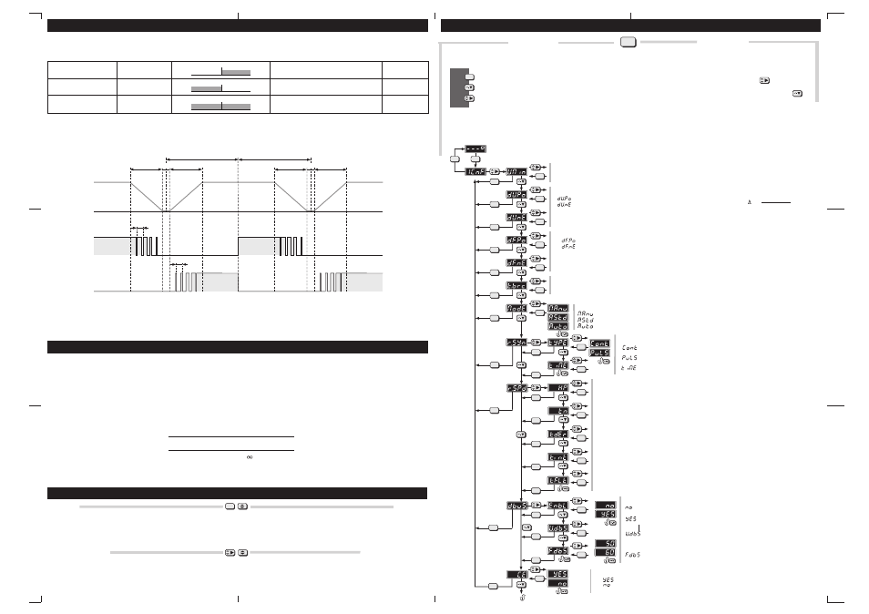
Configuración del SynchroMax / SynchroMax configuration
Password
Pulsando ambas teclas a la vez,durante 10 segundos, permite introducir un pass
word de 4 dígitos. Éste tiene la función de inhabilitar el acceso a la configuración
del equipo. Para deshabilitarlo bastará con repetir el proceso, pero ahora el valor
introducido debe coincidir con el que lo bloqueó. El número de password es
solicitado dos veces consecutivas para evitar errores de entrada.
Valores por Defecto
Pulsando ambas teclas a la vez,durante 20 segundos, los valores de defecto
(fábrica) reempazarán a los programados.
Configuración
Pulsando esta tecla durante 3 segundos, y si el password no está activado,
entraremos en el menú de configuración del equipo. Ahora, y con el uso de
las teclas, podremos navegar por el diagrama de configuración y alarmas
Acepta el valor y desplaza una posición a la izquierda en el árbol
Accept value and move one position at left on the tree
Baja una posición en el árbol
Move one position down on the tree
Desplaza una posición a la derecha en el árbol
Move one position right on the tree
Password
Pressing simultaneously both keys, during 10 second, a 4 digits password can be
set in order to control the acces configuration options. To disable this password
simply repeat the process, but now, the number introduced should be the same
that was used for enable. The password number should be entered twice in
order to avoid mistakes
Default Setup Values
Pressing simultaneously both keys, during 20 second, default setup values
replace user-configured ones.
Configuration
Pressing this key during 3 second ( and there is not any password protection)
we will enter in the configuration menu. Now, using the keyboard, we can
navigate for the configuration and alarms tree
Set
N
A
V
I
G
A
T
I
O
N
Introducir un valor / Setting a value
Para mover ciclicamente por los 4 digitos pulsar
To cyclically move along the four digits press the key
Para modificar el valor del digito seleccionado pulsar repetidamente
To modify the value of the selected digit repeatedly press the key
Introducir el valor de los 4 digitos usando ambas teclas
Set the desired 4 digits value using both above keys
V =
Vgen - Vbb
Vbb
x 100 (%)
Min: Valor mínimo programable
Minimum programmable value
Def: Valor por defecto
Default value
Max: Valor máximo programable
Maximum programmable value
= (+%) Porcentaje positivo / Positive percentage (Min:1, Def:10, Max:25%)
= (+Hz) Diferencia positiva / Positive difference (Min:0, Def:0.5, Max:1.0Hz)
= (- %) Porcentaje negativo / Negative percentage (Min:1, Def:10, Max:25%)
= (- Hz) Diferencia negativa / Negative difference (Min:0, Def:0.0, Max:1.0Hz)
Es posible tener un margen asimétrico, por ejemplo, aceptar que la tensión de grupo sea un 10% mayor pero sólo un 5% menor que la principal
It´s possible to have a asymmetric margin, for example, to accept that the generator voltage will be a 10% higher but only 5% lower than the busbar
Es posible tener un margen asimétrico, por ejemplo, aceptar que la frecuencia de grupo sea 1Hz mayor pero sólo 0,2Hz menor que la principal
It´s possible to have a asymmetric margin, for example, to accept that the generator frequency will be 1Hz higher but only 0.2Hz lower than the busbar
Configuración habilitada / Enabled configuration
Configuración deshabilitada / Disabled configuration
Si la configuración esta deshabilitada, podrá visualizarse ésta pero no modificarse.
If the configuration is disabled, you can show it but can´t modify it
Valor minimo de tension principal / Minimum busbar voltage (Min: 80, Def: 320, Max: 600V)
Por debajo de este valor no se hará sincronización ni control de velocidad.
Under this value no synchronization neither speed control will be doned
Tiempo del contactor / Breaker response time (Min: 0, Def: 80, Max: 1000msec)
Retardo de tiempo que transcurre desde la excitación de la bobina del contactor hasta el cierre de los contactos
Delay time since the breaker coil is excited until the contacts are closed
Banda proporcional Xp / Xp Proportional band (Min: 0.2, Def:2.5)
Banda de cálculo proporcional / Proportional operation band
Reles de control de velocidad / Speed control relays
Rele de sincronismo/ Synchronism relay (Def:Cont)
Función de bus muerto / Dead bus function (Def:No
enabled
)
Configuración habilitada / Enabled configuration
Conectado continuamente mientras se dan condiciones de sincro / Conected
continuously while synchro conditions are fulfilled
Pulso mientras se dan condiciones de sincro / Pulse while synchro conditions
are fulfilled
Duración máxima del pulso / Maximum pulse time (Min: 1, Def:1, Max: 10sec)
Función deshabilitada / Disabled function
Función habilitada / Enabled function
Máxima tensión para considerar bus muerto / Maximum voltage for consider dead
bus (Min: 0, Def: 0, Max: 600V)
Frecuencia de referencia para control de velocidad del generador / Reference
frequency for speed generator control (Def: 50Hz)
Tiempo de ciclo de los contactores Tn / Tn (Min: 200, Def:500, Max: 3000msec)
Tiempo entre dos pulsos de regulación / Time between regulation pulses
Tiempo de acción derivativo Td / Td derivative time (Min: 0.00, Def:0.00, Max: 99.99s)
Constante del termino derivativo del control PID, para anular su acción hay que programarla a 0.
Derivative constant of the PID control, to annul his action it is necessary to programme 0.
Tiempo de acción integral Ti / Ti Integral time (Min: 0.0, Def:999.9, Max: 999.9s)
Constante del termino integral del control PID, para anular su acción hay que programarla a 9999
Integral constant of the PID control, to annul his action it is necessary to programme 9999.
Tiempo de filtro Tflt / Tflt (Min: 0, Def:0, Max: 3000s)
Tiempo del filtro pasa bajos que se aplica a la señal de entrada del PID /
Time of the filter that is applied in the input sign of the PID.
Máximo diferencia de tensión aceptable (+/- %) / Maximum acceptable voltage difference (+/- %)
Máximo diferencia de frecuencia aceptable (+/-Hz) / Maximum acceptable frequency difference (+/- Hz)
Manual (sólo visualiza) / Manual (only display)
Asistida (se requiere confirmación del usuario)/ Assisted (operator confirm requested)
Automática (conexión totalmente automática)/ Automatic (completely automatic operation)
Modo de Trabajo / Operation mode ( Def: MAnu)
Nota / Note:
Mientras estemos dentro del menú de configuración quedarán desactivadas
todas las funciones del Synchromax.Por el contrario si tenemos activado el
rele de sincronismo, quedará desactivado el acceso al menú.
While we are in to the configuration menu all the Synchromax functions will
be deactivates.On the contrary if the syncro relayis connected the
configuration acces will be disabled.
FsetP
(Frecuencia Grupo sobre principal / Generator frequency over busbar)
Frecuencia que el generador debe alcanzar por encima de la frecuencia principal
Frequency that the generator should be achieve over the busbar frequency
FsetN
(Frecuencia Grupo bajo principal / Generator frequency under busbar)
Frecuencia que el generador debe alcanzar por debajo de la frecuencia principal
Frequency that the generator should be achieve under the busbar frequency
Fbb
(Frecuencia principal / Busbar frequency)
El control de la frecuencia de grupo se harácon respecto a Fbb
The generator frequency control will be done with respect to Fbb
Xt
(Banda muerta / Dead band : +/-0.05Hz)
Banda dentro de la cual no se generarán pulsos de aceleración ni de deceleración
Band within no speed up neither speed down pulses will be generated
El nuevo SynchroMax permite obtener la sincronización con frecuencia de grupo
superior, inferior ó indistintamente respecto a la principal.
Por ejemplo, si queremos:
Aplicación Standard. Si los valores programados en dFnE y dFPo son pequeños
(0,10Hz) tendremos una muy precisa sincronización pero requeriremos más tiempo.
Aplicación de Emergencia.Si los valores programados en dFnE y dFPo son grandes
(1.00Hz) obtendremos muy rapidamente la sincronización pero será menos precisa.
The new SynchroMax permits to have synchonization with generator frequency
higher, lower or indifferently with respect the bus bar.
For axample, if we want:
Standard Application. If the programed values in dFnE and dFPo are low
(0.10Hz) we will have a very precise synchronization but more time will required..
Emergency Application.If the programed values in dFnE and dFPo are high
(1.00Hz) we achieve quickly the synchronization but it will be less precise.
Caracteristicas de Syncronización / Synchonization Characteristics
Sintonización del PID / PID Synchronization
Configuración del SynchroMax / SynchroMax configuration
Set
Set
Set
Set
Set
Set
Set
Set
Set
Set
Set
Set
Set
Set
Set
Set
Set
Set
Set
Set
Set
Set
Set
Set
Set
Set
Set
Set
Set
Set
Set
Set
Set
Set
Set
Set
Set
Set
Set
Set
Set
Set
Set
Fg siempre mayor que Fbb
Fg always higher than Fbb
Fg siempre menor que Fbb
Fg always lower than Fbb
Fg mayor ó menor que Fbb
Fg higher or lower than Fbb
Fbb<Fg<Fbb+0,5
Fbb-0,5<Fg<Fbb
Fbb-0,5<Fg<Fbb+0,5
Fg debe estar entre Fbb y Fbb+0,5Hz
Fg should be between Fbb & Fbb+0.5Hz
Fg debe estar entre Fbb y Fbb-0,5Hz
Fg should be between Fbb & Fbb-0.5Hz
Fg debe estar entre Fbb-0,5 y Fbb+0,5Hz
Fg should be between Fbb-0.5 & Fbb+0.5Hz
dFnE = 0.00Hz
dFPo = 0.50Hz
dFnE = 0.50Hz
dFPo = 0.00Hz
dFnE = 0.50Hz
dFPo = 0.50Hz
Fbb
Fg (ok)
-0.5Hz
Fbb
Fg (ok)
Fg (ok)
+0.5Hz
-0.5Hz
Fbb
Fg (ok)
+0.5Hz
Acelerar
Speed Up
FsetP
FsetN
dFPo
dFnE
Fbb
Fg
Decelerar
Speed Down
Xp
Xp
Xp
Xp
Xt
Xt
tn
tn
Generator Frequency
Busbar Frequency
Controlador Xp Ti Td
P 2Xc 0
PI 1/0.45Xc 1/1.2Tc 0
PID 1/0.6Xc 0.5Tc 0.125Tc
Existen muchos metodos para el calculo de Xp, Td y Ti ya sea de forma empírica
o analítica. Los más clásicos son los métodos Ziegler-Nichols tanto a partir de la
respuesta escalón como de la respuesta en frecuencia.
El método de Ziegler-Nichols basado en la respuesta en frecuencia consiste en
lo siguiente:
Primero se anula a acción integral (poniendo Ti = 99.99) y derivativa (Td = 0) y
usamos solamente la acción de control proporcional Xp. Incrementamos Xp
desde 0 hasta un valor critico Xc en la cual la salida exhiba por primera vez
oscilaciones sostenidas. Así se determina experimentalmente la banda
proporcional Xc y el período correspondiente Tc.
A partir de estos valores Ziegler y Nichols sugirieron fijar los valores de Xp, Ti y
Td.
Many methods exist for the calculation of Xp, Td and Ti. The most classic are
the methods Ziegler-Nichols.
The method of Ziegler-Nichols based on the response on frequency consists
of the following thing:
First, annul the integral ( Ti = 99.99) and derivative action (Td = 0) and use only
the action of the proporcional control Xp. Increase Xp from 0 up to a critical
value Xc whose exit takes supported oscillatons as the first time. This way we
determine the proporcional band Xc and his period Tc.
With these values Ziegler and Nichols calculated Xp, Ti and Td.
according to the following table: