CIRCUTOR TR16 Series User Manual
Page 2
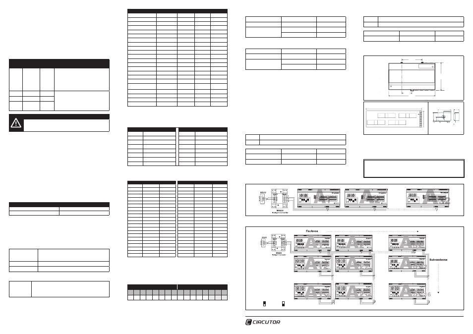
5.4.2 Sub-slave devices
For communications systems with slaves and sub-slaves (DIAGRAM B. Connection
diagram of the RS-485 slave and sub-slave communications bus), the communica-
tions of the devices marked as sub-slave (A
1
2
, A
2
2
,,, A
32
2
... A
1
16
, A
2
16
,,, A
32
16
) must
have different settings and a node numbering system in order.
The slave nodes (A
1
, A
2
... A
32
), the same as specified in the previous section, can
be numbered from peripheral 1 to 255 (from 01 to FF in hexadecimal). On the other
hand, the sub-slave nodes of each of the communications buses, must be numbe-
red from 2 to 16 (from 02 to 10 in hexadecimal), and consecutively in each of their
related buses. The slave devices cannot detect the presence of sub-slave devices
with node numbers above 16 (10 in hexadecimal).
Equip-
ment:
Switch 3
Decimal
Node
A1
ON
01
The numbering of the node numbers may
vary between 1 and 255 (from 01 to FF
in hexadecimal). Under no circumstances
may they be duplicated, and they need
not be assigned in a logical or sequential
order.
A1
2
OFF
02
The numbering of the node numbers
may vary between 2 and 16 (from 02 to
10 in hexadecimal) and must be sequen-
tial, without leaving any node numbers
unassigned.
...
OFF
--
A1
16
OFF
16
IMPORTANT!
If new sub-slaves are added, the slave device must be reset
(leading bus: A
1
, A
2
... A
32
). For example, if device A
2
3
is added,
device A
2
must be reset.
This operation is required so that the leading element performs a scan of the entire
communications bus an implements all the information from its sub-slave devices
in its memory map.
5.5 Analogue input and temperature probe
The
TR16-RS485 is equipped with an analogue input to connect a probe or an
industrial sensor. The analogue input behaves in a linear manner, delivering by
transmission the analogue measurement in resolution dots (from 0 to 1024 dots).
The communications master is responsible for converting the said dots to physical
values that the user can understand.
Moreover, the equipment has an input for the connection of a Pt100 or Pt1000 type
temperature probe. To connect one or the other type of probe (Pt100 or Pt1000),
it must be selected by using the fourth switch located on the front panel. Once the
switch has been set, the equipment sends the temperature value in degrees centi-
grade by communication.
Temperature probe
Switch 4
Pt100
ON
Pt1000
OFF
5.6 Modbus protocol
The
TR16-RS485 peripheral uses the MODBUS© protocol. Within the MODBUS©
protocol, the RTU (Remote Terminal Unit) mode is used; every 8-bits per byte in a
message contains two 4-bit hexadecimal characters.
The format for each byte in RTU mode is:
Code
8 binary bits, hexadecimal 0-9, A-F
2 hexadecimal characters contained in each 8-bit field
of the message.
Bits per byte
8 data bits
Check-Error field
CRC (Cyclical Redundancy Check) type
Implemented Modbus functions:
Functions 03
and 04
Function used for reading the parameters measured by the
TR16-RS485. All the electric parameters are 16 bit words,
so that to request each parameter one Word (2 bytes – XX)
is needed.
5.6.1 Modbus/RTU® memory map
This table shows the Modbus addresses of the conventional slave device. In the
successive tables (from module 2 on), the memory addresses are displayed for the
sub-slave devices, if these are connected.
Description
Abbreviation
Symbol
Address
Unit
Input current 1
M1-MLC1
I 1
0000
A x 100
Input current 2
M1-MLC2
I 2
0001
A x 100
Input current 3
M1-MLC3
I 3
0002
A x 100
Input current 4
M1-MLC4
I 4
0003
A x 100
Input current 5
M1-MLC5
I 5
0004
A x 100
Input current 6
M1-MLC6
I 6
0005
A x 100
Input current 7
M1-MLC7
I 7
0006
A x 100
Input current 8
M1-MLC8
I 8
0007
A x 100
Input current 9
M1-MLC9
I 9
0008
A x 100
Input current 10
M1-MLC10
I 10
0009
A x 100
Input current 11
M1-MLC11
I 11
000A
A x 100
Input current 12
M1-MLC12
I 12
000B
A x 100
Input current 13
M1-MLC13
I 13
000C
A x 100
Input current 14
M1-MLC14
I 14
000D
A x 100
Input current 15
M1-MLC15
I 15
000E
A x 100
Input current 16
M1-MLC16
I 16
000F
A x 100
Differential Voltage
M1-VDG
Vd
0010
V x 10
Pt100/Pt1000
temperature
M1-TEMP
Pt100/Pt1000
0011
ºC
Analogue input
M1-ANAL
0012
Dots
Digital inputs
M1-DIG
0013
0 / 1
Not used
0014
Peripheral number
M1-PERIPH
0015
In the successive tables (from sub-slave 2 on), the initial addresses of the modules
are shown, taking into account that they all have the same distribution available to
the leading bus device.
Module
Addresses
Module
Addresses
2
0016 to 002B
10
00C6 to 00DB
3
002C to 0041
11
00DC to 00F1
4
0042 to 0057
12
00F2 to 0107
5
0058 to 006D
13
0108 to 011D
6
006E to 0083
14
011E to 0133
7
0084 to 0099
15
0134 to 0149
8
009A to 00AF
16
014A to 015F
9
00B0 to 00C5
Examples of the memory addresses of some of the sub-slave devices, if these are
connected.
Module 2
Address
UDS
Module 3
Address
UDS
M2-MLC1
0016
A x 100
M3-MLC1
002C
A x 100
M2-MLC2
0017
A x 100
M3-MLC2
002D
A x 100
M2-MLC3
0018
A x 100
M3-MLC3
002E
A x 100
M2-MLC4
0019
A x 100
M3-MLC4
002F
A x 100
M2-MLC5
001A
A x 100
M3-MLC5
0030
A x 100
M2-MLC6
001B
A x 100
M3-MLC6
0031
A x 100
M2-MLC7
001C
A x 100
M3-MLC7
0032
A x 100
M2-MLC8
001D
A x 100
M3-MLC8
0033
A x 100
M2-MLC9
001E
A x 100
M3-MLC9
0034
A x 100
M2-MLC10
001F
A x 100
M3-MLC10
0035
A x 100
M2-MLC11
0020
A x 100
M3-MLC11
0036
A x 100
M2-MLC12
0021
A x 100
M3-MLC12
0037
A x 100
M2-MLC13
0022
A x 100
M3-MLC13
0038
A x 100
M2-MLC14
0023
A x 100
M3-MLC14
0039
A x 100
M2-MLC15
0024
A x 100
M3-MLC15
003A
A x 100
M2-MLC16
0025
A x 100
M3-MLC16
003B
A x 100
M2-VDG
0026
V x 10
M3-VDG
003C
V x 10
M2-TEMP
0027
ºC
M3-TEMP
003D
ºC
M2-ANAL
0028
Dots
M3-ANAL
003E
Dots
M2-DIG
0029
0 / 1
M3-DIG
003F
0 / 1
Not used
002A
0040
M2-PERIPH
002B
M3-PERIPH
0041
5.6.2 Reading of the status of the digital inputs (DIG)
The DIG variable, like the rest of the electric variables, is a record (1 word = 2 bytes),
in other words, in hexadecimal it would be 0xFFFF. The inputs go from 1 to 3 and
these represent the 3 lower weight bytes:
HIGHEST WEIGHT BYTES
LOWEST WEIGHT BYTES
7
6
5
4
3
2
1
0
7
6
5
4
3
2
1
0
0
0
0
0
0
0
0
0
0
0
0
0
0
I3
I2
I1
To know the Modbus memory addresses, refer to section 05.06.01 Memory map.
The value of each input determines if it is activated (1) or deactivated (0).
Example 1 (in master device):
TX
NP 0400090001 CRC
Input activated
3
By communication
INP=0x0004
Hexadecimal
0000000000000100
Binary
Example 2 (in master device):
TX
NP 0400090001 CRC
Input activated
2 and 3
By communication
INP=0x0006
Hexadecimal
0000000000000110
Binary
5.6.3 Reading the peripheral number
The PERIPH variable, like the rest of the electric variables, is a record (1 word = 2
bytes), in other words, in hexadecimal it would be 0xFFFF. This record refers to the
peripheral number associated by using the front panel on the equipment, for each
of the slave and sub-slave devices.
5.6.4 Number and listing of sub-slave devices connected
Number of sub-slave devices: There is a Modbus record (0834), which indicates
the number of sub-slave devices connected to the communications master (see in
DIAGRAM B, devices, A
2
... A
16
). Said variable solely returns the numeric value in
hexadecimal, reporting the number of nodes connected to the device through the
master communications port (if it is used).
Example 1:
TX
NP 0408340008 CRC
RX
NP 0402 0006 CRC
Number of slaves
6
By communication
RX = 0x0006
Hexadecimal
Decimal conversion
6
Decimal
Listing of sub-slave devices: As opposed to the number, the listing of sub-slave
elements connected to a master device, reports one by one, the peripheral numbers
connected to the said master device (record 07D0).
Example 1:
TX
NP 0407D0000F CRC
RX
NP 0420 02 03 04 05 06 00 00 00 00 00 00 00 00 00 00 00 CRC
Listing of slaves
02, 03, 04, 05, 06
Hexadecimal
Decimal conversion
02, 03, 04, 05, 06
Decimal
6. DIMENSIONS
106.0
6/1
Multi-purpose clips for
x
y
x
y
y
99
.8
30.2
60.6
(pitch of wall mounting holes in din rail clips)
160.0
9/1
113.8
56.9
99
.8
y
160
45
+12V
S5/S1
GND
GND
S6/S2
S7/S3
S8/S4
+15V -15V O/P
40.0
15
.
5
22.5
25.0
12.5
10.0ø
7. TECHNICAL ASSISTANCE SERVICE
If you have any doubts about the operation of the equipment or any malfunction,
please contact the technical assistance service at
CIRCUTOR SA
CIRCUTOR, SA - Technical Assistance Service
Vial Sant Jordi, s/n - 08232 Viladecavalls (Barcelona) SPAIN
Tel.: 902 449 459 (Spain) - +34 93 745 29 00
email: [email protected]
DIAGRAM A - Connection diagram of the RS-485 communications bus with slave devices (conventional bus)
DIAGRAM B - Connection diagram of the RS-485 communications bus with slave and sub-slave devices
SWITCH ON
SWITCH OFF
M98234101-03-15A