Conta-electronics – CONTA-CLIP CMS-110A-UI User Manual
Page 2
CONTA-ELECTRONICS
=====
=
=
=
=
=
=
=
=
=
CMS
CMS
CMS
CMS----I10A
I10A
I10A
I10A----UI
UI
UI
UI
=
=====
=====
=====
=====IIIIsolated
solated
solated
solated S
S
S
Signal
ignal
ignal
ignal converter
converter
converter
converter
Further information:
www.conta-clip.com
Cat. No.: 95120.0
Further information:
www.conta-clip.com
Configuration
Configuration
Configuration
Configuration
Dipswitch settings
Dipswitch settings
Dipswitch settings
Dipswitch settings
=
To open the module press the locking levers under the terminals
with a screwdriver.
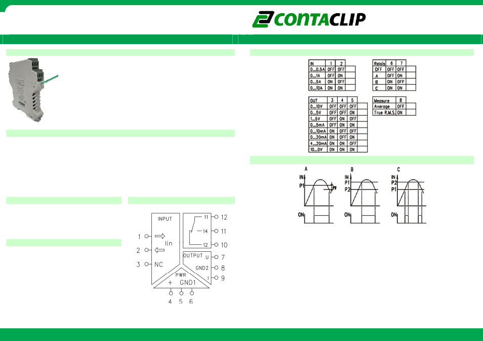
The module is configured by setting the dip-switches according
to the table on the side of the module.
The switching threshold of the relay can be adjusted using
potentiometers P1 and P2. The switching diagram is shown on
the side of the module.
=
Measuring principle
Measuring principle
Measuring principle
Measuring principle
=
=
=
Relay switching diagram
Relay switching diagram
Relay switching diagram
Relay switching diagram
=
Average:
Average:
Average:
Average:
The average of a number of measurements taken from a DC current. When measuring
the average of an AC current the result will be ‘0’.
True R.M.S.:
True R.M.S.:
True R.M.S.:
True R.M.S.:
The effective value of an AC current. This is an equivalent to a DC current that would
provide the same amount of heat generated in a resistor as the AC current would if
applied to that same resistor.
==
=
Connecting the module
Connecting the module
Connecting the module
Connecting the module
Co
Co
Co
Connection diagram
nnection diagram
nnection diagram
nnection diagram
=
The pin configuration for I/O and power
connection is shown on the top of the
module. The green Led on top indicates
Power ON.
=
Calibration
Calibration
Calibration
Calibration
The zero value of the module can be
calibrated by pressing and holding the
calibration button on top of the module
until the Led flashes.
During calibration the input should be
disconnected or there should be a
referenced ‘0’ connected to the input of
the module.
=
=
=
=
=
=
=
Set the threshold value of potentiometer P1 and P2 by using a screwdriver.
Both potentiometers represent a percentage from the selected input value.
Full left turn is 0% and full right turn is 100% of the selected input value.
A:
A:
A:
A: The relay switches on when value P1 is reached. The relays switches off when
value P1 - P2 is reached.
B:
B:
B:
B: The relay switches on when value P1 is reached. The relays switches off when
value P2 is reached.
C:
C:
C:
C: The relay switches on between P1 and P2.
=====