Crompton Controls CRA40/32 User Manual
Page 2
Wiring Min. Max. :
Control Circuit Test (Trip Test):
Test
98
97
96
95
+
3
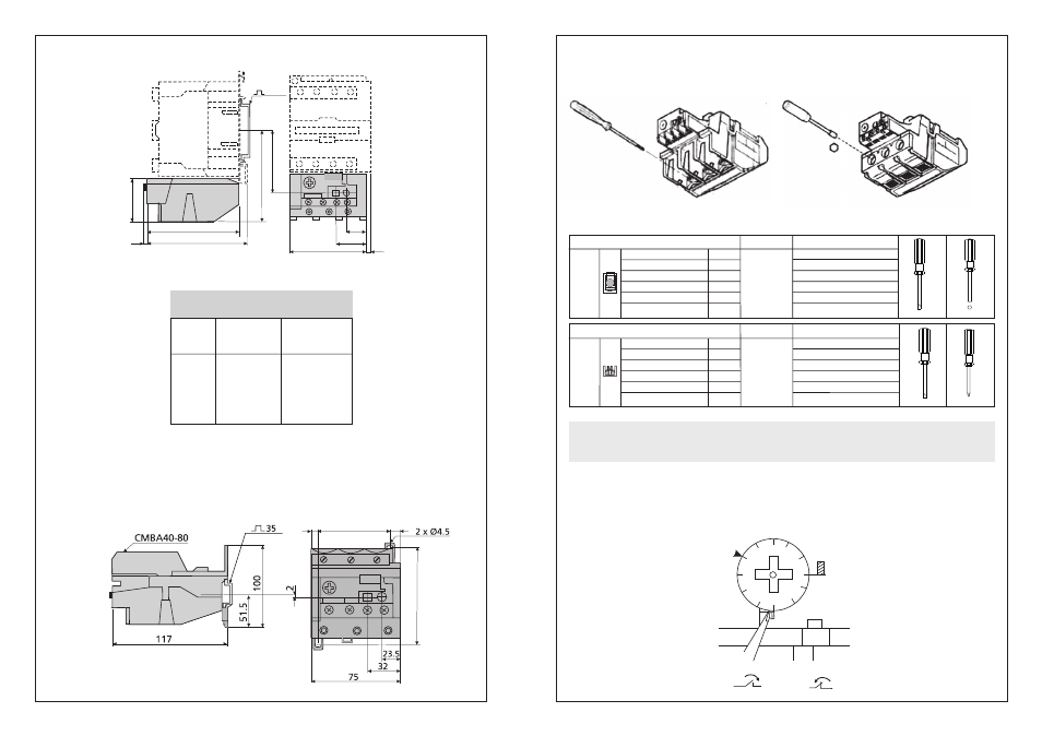
Dimensional Diagram:
2
a
b
c
g (3P)
g (4P)
CC+CRA40~80
CC40
CC50
CC65
111
119
72.4
4.5
9.5
CC80
115.5
123.5
76.9
9.5
15
Wiring Capability:
Auxiliary Terminals
Solid Wire
Stranded Wire
AWG Wire
Standard Guage
Tightening Torque
Tightening Torque(UL)
Screw Plate
Combi-head
(Slot/Philips)
Head Type
2 x 1...2.5
2 x 0.75...1.5
2 x 18...14
A2 / B2
1.2 / 10.6
7
CRA40~80
2
mm
2
mm
Nm/lb.in
lb.in
Philips No.2
Ø 6
4
Load Terminals
Solid Wire
Stranded Wire
AWG Wire
Standard Guage
Tightening Torque
Tightening Torque(UL)
Clamp
Head Type
2 x 4...25
2 x 4...25
2 x 12...2
2 x A4..B9
9 / 79.5
75
CRA40~80
2
mm
2
mm
Nm/lb.in
lb.in
Ø 6
Slot/Hex.Socket Head
Terminal screws must be tightened at recommended torque and checked frequently.
All strands of cable shall go into the terminal of each phase.
CAUTION
a
c
6
54
109
70
30
g
21
b
35/75
Independent Mounting:
75/87
=
=
50