Connection diagram – Crompton Controls CIMR-VC4A0001BAA User Manual
Page 6
6
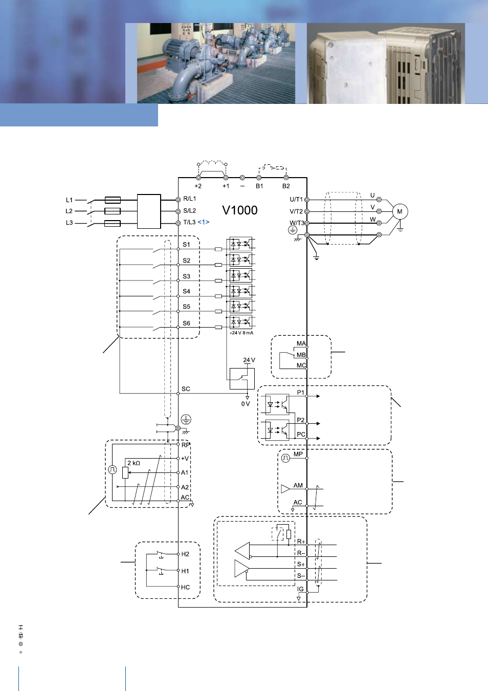
YASKAWA V1000
DC reactor
(option)
Thermal
relay
Braking resistor
(option)
External fault
Fault reset
Multi-speed step 1
Multi-speed step 2
Reverse / Stop
Forward / Stop
Link
Shielded
Cable
Ground
During run
Shield ground
terminal
DIP
switch S3
Pulse Input
(max. 32 kHz)
Analog input power supply
+10.5 max. 20 mA
Multi-function analog input 1
0 to +10 V (20 kΩ)
Multi-function analog input 2
0 to +10 V (20 kΩ)
0/4 to 20 m A (250 Ω)
Monitor outputs
(default setting)
Terminal resistance
(120 Ω, 1/2 W)
MEMOBUS comm.
RS-485/422
max. 115 kBps
Multi-function pulse / analog inputs
(default: frequency reference)
Power
Supply
Multi-function photo-
couplee output
48 Vdc, 2 to 50 mA
(default setting)
Fault
Photocoupler
output common
Frequency agree
Pulse train output
(max. 32 kHz)
(Output frequency)
Analog output
0 to +10 VDC (2 mA)
(Output frequency)
t
Multi-function relay output
250 VAC / 30 VDC (10 mA to 1 A)
(default setting)
Fuses
Main
Switch
Filter
Multi-function
digital inputs (default
setting)
SINK
SOURCE
Safe Disable
inputs
Connection Diagram
Use twisted pair cables.
Use shielded twisted pair cables.
Indicates a main circuit terminal.
Indicates a control circuit terminal.