CRU DE100 IDE Carrier and Frame User Manual
Rugged, reliable, mobile, secure
Rugged, Reliable, Mobile, Secure
TM
1-800-260-9800
www.CRU-DataPort.com
DE100i-A100 Install Guide
Removable Ultra ATA133 Drive Enclosure
Master/Slave Selection Jumper (J5)
Master Drive configuration (Factory Default). Forces master drive
configuration on receiving frame. Change jumper to set slave
drive configuration.
Device Spin Down/Up Timer (J6)
Jumper installed (Factory Default) enables device spin down/
up visual indicator. Receiving frame unit ID number display will
flash to indicate device spin down/up.
Receiving Frame Motherboard (Rear View)
Master/Slave Configuration Jumper J5 (Receiving Frame
Motherboard)
In most cases, the drive will be factory-configured as a Master
Ultra ATA133 drive using a jumper plug on the drive itself. No
configuration changes are required. For multiple drive configura-
tions, it is necessary to set the first Ultra ATA100 drive as Master
and the second Ultra ATA133 drive to Slave. This can be done
by changing the jumper on the Ultra ATA133 drive itself (refer to
your drive manufacturer documentation for further information).
Select the Master/Slave configuration on the rear of the receiving
frame by placing a jumper on the appropriate J5 pins. Remove the
jumper if you wish to use the Unit ID Select switch on the receiv-
ing frame to configure the Master/Slave drive selection.
NOTE: The unit ID select switch configures the unit ID
number display only. The master/slave setting must be set
on the drive itself (refer to the drive manufacturer’s docu-
mentation for further information).
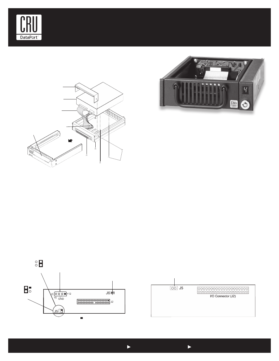
Drive Installation Overview
Drive Carrier Circuit Board
Drive
Carrier
#6-32 Phillips
F.H. Screw
(6 total)
Receiving
Frame
Receiving Frame
Motherboard
Power Cable
I/O Cable
Disk Drive
(not included)
Cable Cover
(provided)
Drive Activity Indicator
Connector (J5)
Device Spin Down/Up Jumper (J6)
On (factory default) = Device Spin
Down/Up Activity Indicator Enabled
Off = Device Spin Down/Up
Activity Indicator Disabled
DC Power
Slave Drive
Select (1)
Master Drive
Select (0)
(Factory Default)
J5
J5
= Pin 1