CRU DE200 SCSI User Manual
Rugged, reliable, mobile, secure
Rugged, Reliable, Mobile, Secure
TM
1-800-260-9800
www.CRU-DataPort.com
DE200 Ultra160 68-Pin Install Guide
Removable SCSI Wide Ultra160 Drive Enclosure with 68-Pin Interface
Installation
1. Locate the ID select jumper positions on the drive, and remove any
jumpers plugs installed (the DE200 Ultra160 68-Pin drive carrier board
will plug into this section of the drive).
2. Carefully insert the drive into the carrier. Slide the drive towards the drive
carrier board, so that the I/O, DC power, and ID select connectors on the
drive mate with their respective connectors on the drive carrier board.
NOTE: The DE200 Ultra160 68-Pin carrier supports most 68-pin SCSI
Ultra160 interfaces, except Fujitsu Alegro 6 10K RPM drives (these
drives have different spacing between the 68-pin and DC power con-
nectors and will not mate with the drive carrier board).
3. Fasten the drive into place with four (4) #6-32 Phillips Flat Hd. screws
(provided).
Rear Panel
Remote Unit ID Selection: Pins 1-8 are provided for remote unit ID
selection for the computer system or expansion chassis. Remote ID
selection requires that the unit ID switch located on the inside of the
receiving frame be set to “0” (onboard ID selection is set with a switch
located on the inside of the receiving frame).
Enable Termination Power Connector (J4): This jumper is installed at the
factory and enables termination power to/from the SCSI bus.
NOTE: Do not remove this jumper!
Factory-Installed Jumpers (J3): There are two (2) jumpers factory-
installed on J3. One jumper is located on Pins 7 & 8, the other on Pins
9 & 10.
NOTE: Do not remove jumpers! (Remove only if attaching the
DX1/200-SWC160/RH Isolator/Repeater Board. Refer to the full
version of the User’s Guide for further information.)
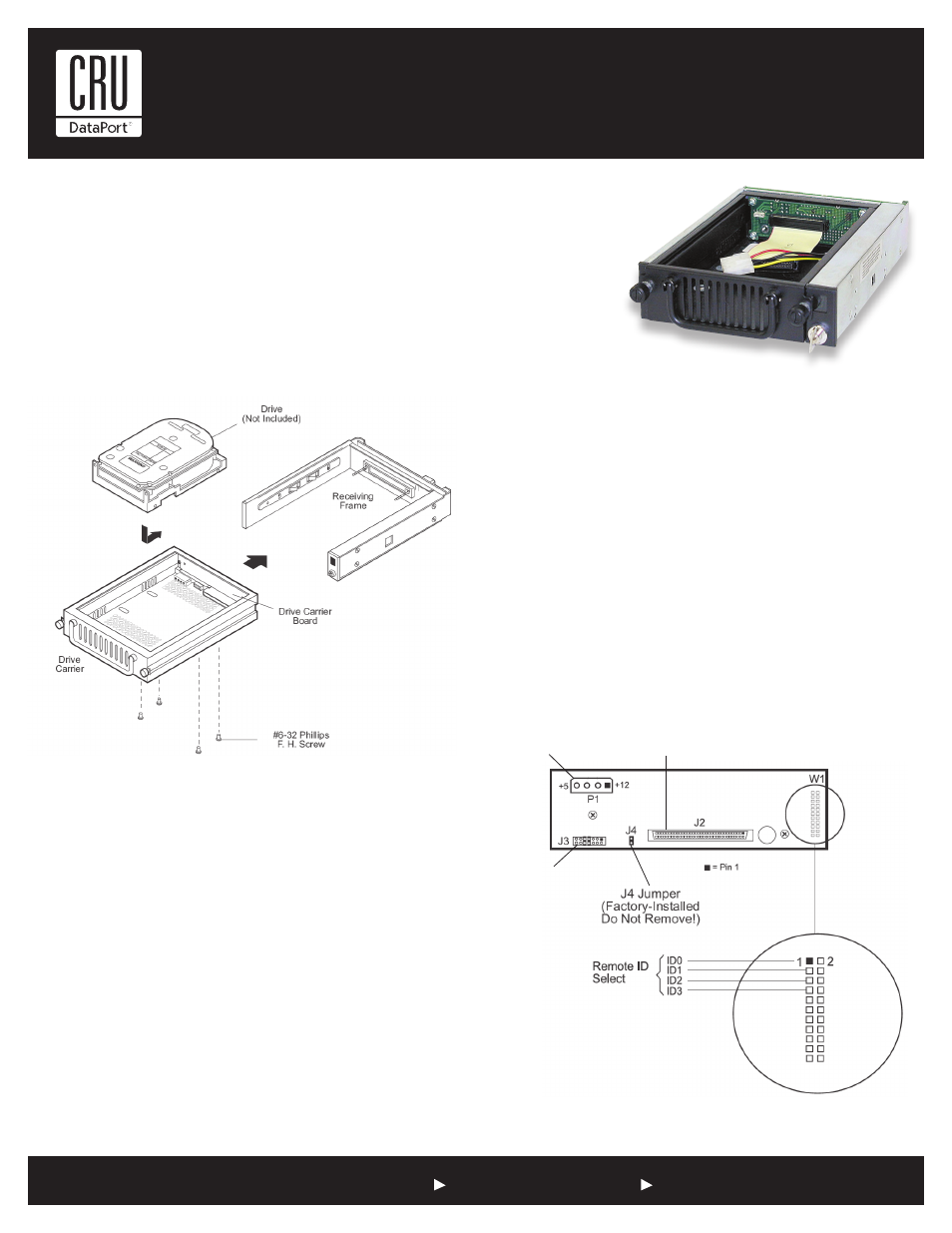
Figure 1: Drive Installation Assembly
Notes: The DE200 Ultra160 68-Pin carrier supports most 68-pin
SCSI Ultra160 interfaces, except Fujitsu Alegro 6 10K RPM drives
(these drives have different spacing between the 68-pin and DC
power connectors and will not mate with the drive carrier board).
For SCSI Ultra160 operation, the DE200 requires Ultra160 chassis
and cabling.
DC Power
Connector
(P1)
(4 each)
68-Pin I/0 Connector
(J2)
Option Pin
Connector
(W1)
J3 Jumpers
(factory-installed
on Pins 7 & 8 and
Pins 9 & 10 - do
not remove)
Figure 2: Receiving Frame Motherboard (rear view)