CRU DE200 SCSI User Manual
Rugged, reliable, mobile, secure
Rugged, Reliable, Mobile, Secure
TM
1-800-260-9800
www.CRU-DataPort.com
Data Express DE200 Ultra160 SCA Install Guide
Removable SCSI Wide Ultra160 Drive Enclosure
Note: Installation of drive cover is necessary for proper fan air flow.
Option Pin Connector (W1)
Remote Unit ID Selection: Pins 1-8 of this connector are provided for
remote unit SCSI ID selection through the computer system. Remote
ID selection requires that the unit ID switch located on the inside of the
receiving frame be set to “0”. (Onboard ID selection is set with a switch
located on the inside of the receiving frame.)
Factory-Installed Jumpers: There are three (3) jumpers factory-
installed on W1. These jumpers are located on pins 9 & 10, pins 19 & 20
and pins 21 & 22.
Note: Do not remove these jumpers.
Fan Fault LED/Alarm Temporary Disable Jumper Option (pins 17 &
18):
No Jumper (Factory Default) – Fan Fault LED and Alarm will both func-
tion when either fan fails.
Jumper on Pins 17 & 18 - When the provided jumper is installed it
will disable both Fan Fault LED and Alarm in the event of a single
fan failure. The Fan Fault LED and Alarm will both function should
the second fan fail.
Note: This jumper must be removed once the faulty fan is replaced.
Enable Termination Power Connector (J4): This jumper is installed
at the factory and enables termination power to/from the SCSI bus.
Note: Do not remove this jumper!
Factory-Installed Jumpers (J3): There are two (2) jumpers factory
installed on J3. One jumper is located on pins 7 & 8, the other is on
pins 9 & 10.
Note: Do note remove jumpers!
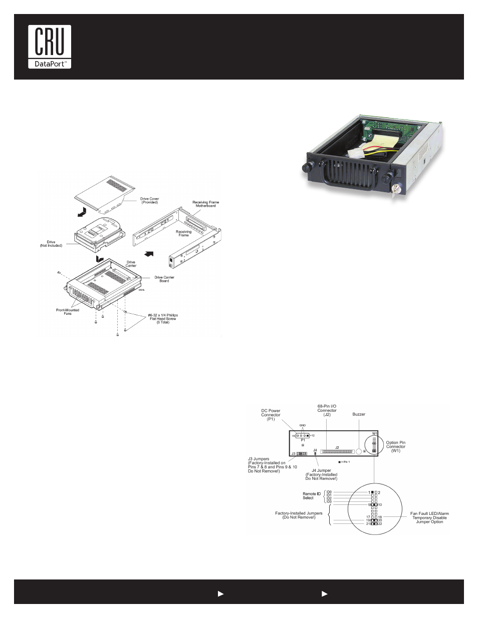
Figure 1: Drive Installation Overview
Notes: For SCSI Ultra 160 operation, the DE200 Ultra160 SCA
requires Ultra160 chassis and cabling.
Figure 2: Receiving Frame Motherboard (rear view)