CRU DE200 SCSI User Manual
Rugged, reliable, mobile, secure
Rugged, Reliable, Mobile, Secure
TM
1-800-260-9800
www.CRU-DataPort.com
DE200 Ultra320 68-Pin Install Guide
Removable SCSI Wide Ultra320 Drive Enclosure
Installation
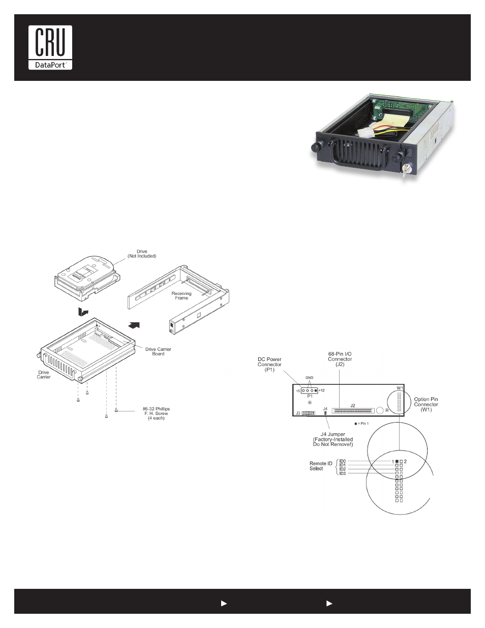
1. Locate the ID select jumper positions on the drive, and remove any
jumper plugs installed (the drive carrier board will plug into this sec-
tion of the drive).
2. Carefully insert the drive into the carrier. Slide the drive towards the
drive carrier board, so that the I/O, DC power, and ID select connec-
tors on the drive mate with their respective connectors on the drive
carrier board.
3. Fasten the drive into place with four (4) #6-32 Phillips Flat Hd.
screws (provided).
Receiving Frame Motherboard
Remote Unit ID Selection: Pins 1-8 are provided for remote unit ID
selection for the computer system or expansion chassis. Remote ID
selection requires that the unit ID switch located on the inside of the
receiving frame be set to “0” (onboard ID selection is set with a switch
located on the inside of the receiving frame; see figure 3).
Enable Termination Power Connector (J4): This jumper is installed at the
factory and enables termination power to/from the SCSI bus.
NOTE: Do not remove this jumper!
Figure 1: Drive Installation Assembly
Notes: For SCSI Ultra320 operation, the DE200 Ultra320 requires
Ultra320 drives, Ultra320 HBA, and Ultra320-compliant cabling
(internal and external).
DE200 Ultra320 can support Ultra320 implementations with a
maximum of fifteen (15) Ultra320 drives (Ultra320 repeater may be
required).
DE200 Ultra320 receiving frames are indicated by their BLUE LED,
while the DE200 Ultra320 carriers are indicated by the Ultra320 logo.
Figure 2: Receiving Frame Motherboard (rear view)