CRU DataPort 10 USB-to-SATA User Manual
Dataport 10 usb-to-sata install guide, Rugged, reliable, mobile, secure
Rugged, Reliable, Mobile, Secure
TM
1-800-260-9800
www.CRU-DataPort.com
Package Contents
1 - DataPort 10 USB-to-SATA frame assembly
1 - DataPort 10 carrier assembly
1 - Metal cover
1 - Internal USB cable
1 - Internal to external USB cable with bracket
4 - #6-32 x 1/4 fl at head screws for drive mounting
4 - M3 x 5 pan head screws for frame installation
2 - Keys for lock
Mounting the Frame in the Computer
1. Turn off the computer and disconnect its power cord from the electri-
cal outlet. Before working on your computer, wait one minute for any
residual energy to dissipate. Ground yourself and then remove the
cover of the computer. Select the 5.25” half-height bay where you plan
to mount the DataPort frame assembly. Remove any fi ller plates that
may be present.
2. To mount the frame assembly in the drive bay:
a. Check the drive bay to see if mounting rails are required (they
should be provided by your computer system manufacturer.) If
required, install one on each side of the frame. Slide the frame
into the computer and check that it is secure.
b. If mounting rails are not required, attach the frame directly to
the PC case using the screws provided. Either the side or bot-
tom mount holes on the frame can be used.
3. For SATA operation, locate a SATA data cable and connect it to the
SATA connector on the frame. For USB operation see Step 4.
4. Locate the USB connector(s) on the system motherboard. Depending
on your system motherboard, it may have one or more 9-Pin USB con-
nectors (with one typically connected to front USB ports on the PC), or
it may have only a 4-Pin USB connector. If your system motherboard
has 9-Pin USB connectors proceed to Step 5. If your system mother-
board only has a Type B USB connector, proceed to Step 6.
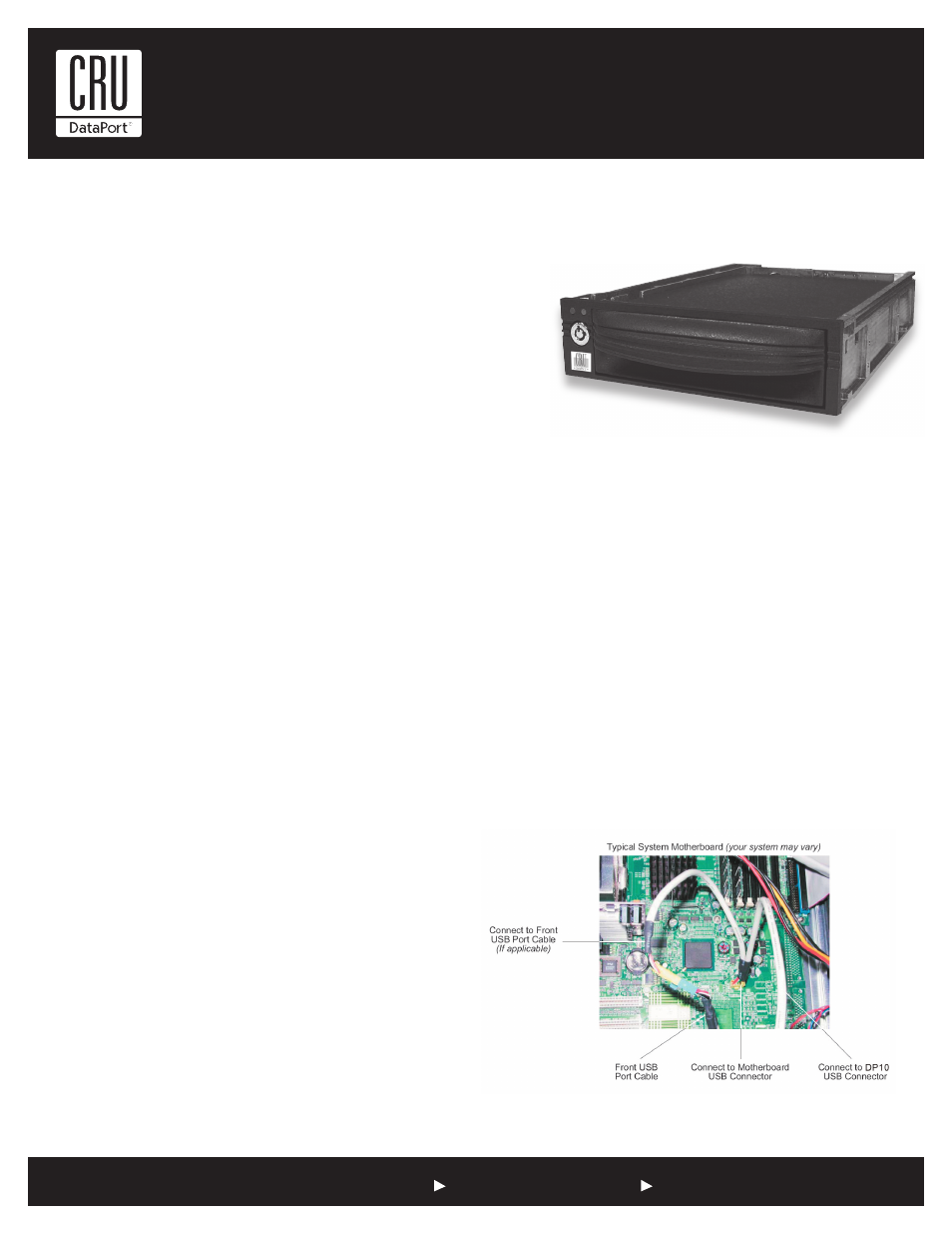
5. Locate a spare 9-Pin USB connector on the system motherboard and
connect the female connector on the split USB cable (provided) to it
(Figure 1).
Note: If your system motherboard has only one 9-Pin USB conetor
and it is connected to the front USB ports, disconnect the front
USB port cable from the system motherboard USB connector.
Connect the female connector on the split USB cable (provided) to
the newly vacated USB connector located on the system mother-
board (Figure 1). If applicable, connect the male connector on the
split USB cable to the front USB port cable (Figure 1). Make sure
the red wires on both cables are correctly aligned.
NOTE: Connecting the DataPort 10 USB-to-SATA to the system
motherboard’s only USB connector will disable one of the front
USB ports (if applicable).
6. If your system only has an available Type B USB connector, remove an
empty PCI slot bracket. Install the Internal USB PCI Bracket. Connect
the USB cable to an available USB port on the back of your computer
chassis and then connect it to your DataPort 10 USB-to-SATA frame.
DataPort 10 USB-to-SATA Install Guide
The New DataPort 10 USB-to-SATA makes data backup and data security easy,
enabling hot-swap (removing the backup hard drive while the system is still on) of
any capacity Serial ATA (SATA) hard disk drive, from a 5.25” (half-height) expansion
bay, while the rugged removable carrier protects your HDD during transport and
storage.
Figure 1: Internal USB Cable