CRU DataPort 25 Hand-Held RAID User Manual
Dataport 25 usb/sata to dual drive sata raid, Rugged, reliable, mobile, secure
Rugged, Reliable, Mobile, Secure
TM
1-800-260-9800
www.CRU-DataPort.com
DataPort 25 USB/SATA to
Dual Drive SATA RAID
Package Contents
1 - DataPort 25 USB/SATA to Dual Drive SATA RAID Frame
1 - DataPort 25 Dual Drive SATA RAID Carrier
1 - Screw kit
1 - Power Adapter Cable
2 - Keys
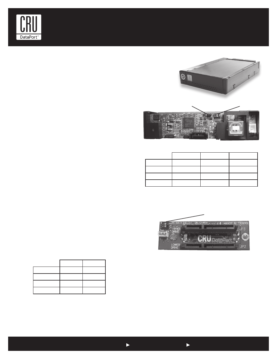
RAID Configuration
The DataPort 25 USB/SATA to Dual Drive SATA RAID operates in four
different configurations. The configuration is determined by the switch
settings on either the back of the frame (see table 1) or the carrier board
(see table 2). To change the configurations set the dip switches to the
desired configuration, then cycle the power on the DataPort 25.
NOTE: When configuration is set on frame the carrier switches
must be set to off and when the configuration is set on carrier the
frame switches must be off and the jumper removed.
For ease of installation it is best to configure the drives to the appropri-
ate RAID array before installing the frame in the enclosure.
NOTE: When changing configurations or setting up a new pair of
drives, the power must be cycled on the DataPort 25.
NOTE: The Host Bus Adapter must support SATA port multipli-
ers for the DataPort 25 USB/SATA to Dual Drive SATA RAID to
use JBOD. Please check Silicon Image’s website (http://www.
siliconimage.com) for supported cards.
The four configurations are 1) Concatenated (two drives capacity together
as a single drive - twice the size of the smallest drive), 2) JBOD, 3) RAID 0
and 4) RAID 1.
NOTE: On the back of the frame board is jumper block J3. If the
jumper is on J3 and the frame is configured as RAID 1, the RAID
will rebuild every time the power is cycled. Remove the jumper
to allow the RAID to power on without rebuilding.
NOTE: If Position 3 is “On” the RAID will rebuild every time the
power is cycled.
Frame Installation
1. Locate an available 3.5” drive bay and remove the front bezel.
2. To mount the frame assembly in the drive bay:
a. Check the drive bay to see if mounting rails are required (they
should be provided by your computer system manufacturer.) If
required, install one on each side of the frame. Then slide the
frame in the computer and check that it is secure.
b. If mounting rails are not required, attach the frame directly to
the PC case using the screws provided. Either the side or bot-
tom mount holes on the frame may be used.
Figure 1: Back of frame
Table 1
Position 1
Position 2
Concatenated
On
Off
JBOD
Off
Off
RAID 1
Off
On
RAID 0
On
On
Position 1
Position 2
J3
Concatenated
On
Off
Off
JBOD
Off
Off
Off
RAID 1
Off
On
*See note below
RAID 0
On
On
Off
Table 2
Carrier Dip
Switch
Frame Dip Switch
J3
Figure 2: Carrier Drive Side