CRU HotPlug Field Kit User Manual
Page 4
CRU-WiebeTech
H o t P l u g U s e r M a n u a l ( A 9 - 0 0 0 - 0 0 3 4 ) R E V 1 . 0
- 4 -
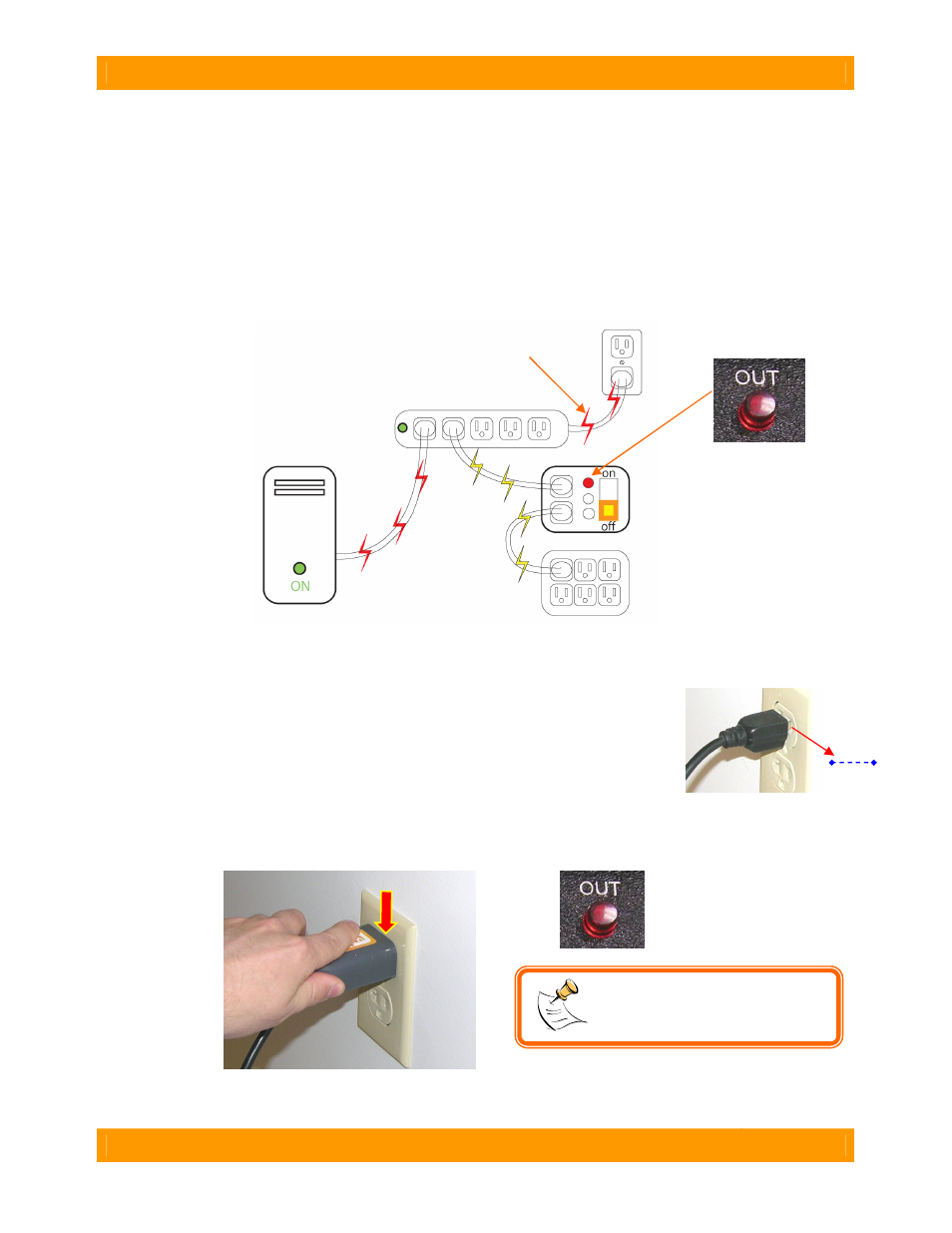
E. You will now establish a connection between HotPlug’s gray output line cord and the computer’s
original source of power. This is done one of two ways, depending on how the computer is
plugged in.
•
If the computer is plugged into a multi-outlet surge protector or power strip:
This is by far the most common configuration you will encounter. First, unplug any unneeded devices
from the power strip from which the computer is currently receiving power. This will reduce power draw
and ensure there is a receptacle available for use with HotPlug. Next, connect the gray output line cord
into the power strip. After you have plugged the output line cord into the power strip, HotPlug’s red LED
(output power indicator) will light.
•
If the computer is plugged directly to a wall outlet
This is less common. You will need to use the Plug Capture Device (PCD) to create the connection.
a. Install the PCD on the free plug end of the output line cord.
b. Next, carefully pull the computer’s A/C plug about 1/8-inch out from the wall.
Do not pull it more than 1/8-inch or the power connection may be broken.
c. Slide the PCD’s end tab between the two power conductors in the plug and
between the wall outlet and the plug. Push down on the PCD until it makes
electrical connection and mechanically seats on the plug. HotPlug’s red LED should light, indicating
that a solid electrical connection is established.
(Red color indicates path of computer’s power)
1/8”
NOTE: You will not be able to
use PCD with European plugs
that have insulated prongs.
UPS
HotPlug
out
in