Monroe Electronics 625A User Manual
Model 625a rf sensor instruction sheet
Model 625A RF Sensor Instruction Sheet
Installation
1. The Sensing Input signal must
be a single TV video modu-lated
signal with a maximum signal
level of +15 dBmV. Use an
external bandpass filter and/or
pad for multiple channel feed
conditions and levels that
exceed +15 dBmV.
2. Connect your single TV video
modulated signal to the Sense
Input. Make sure the level does
not exceed +15 dBmV.
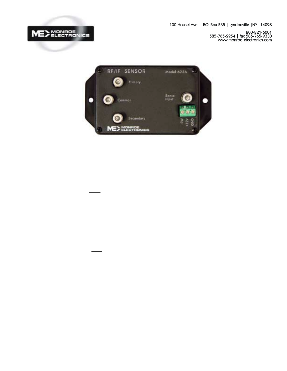
3. Connect your primary RF
source to the primary input and
the alternate RF source to the
secondary input. The common
output is the RF output of the
625A.
4. Attach the White wire of the
power supply provided to the
+12 VDC input and the Black
wire to ground on the 625A.
5. Connect the external contacts
on the connector and ground as
desired, for switching or alarm
signaling.
Operation
The 625A's sensing circuit monitors
the loss of TV video modulated
signal. The absence of the
modulated signal caused the 625A
to automatically switch to the
secondary input. It will remain in this
state until the modulated signal
returns to the sense input causing
the 625A to switch back to the
primary RF input.
Alarm connection goes to ground
through a solid state switch when
secondary is active.
Specifications
RF Isolation
> 60 dB @ 450 MHz.
> 48 dB @ 950 MHz.
Safe Sense Input Level
+15 dBmV maximum
Drop-Out Level
0 dBmV, +0, -3 dB; delay
≈
250
mSec.
Pick-up Level
0 dBmV, +3, -0 dB; delay
≈
20
mSec.
Power Requirement
Input: 100-240 VAC
±
2%, 50/60 Hz
Output: 12 VDC
Physical
5.25"H x 2.75"W x 2"D
Design and specifications are subject to
change without notice
P/N 1340168 (625A/100)
101206