Monroe Electronics 628 User Manual
Model 628 encoder sensor instruction sheet
Design and specifications are
subject to change without notice
628/100 101206
P/N 1340148
Model 628 Encoder Sensor Instruction Sheet
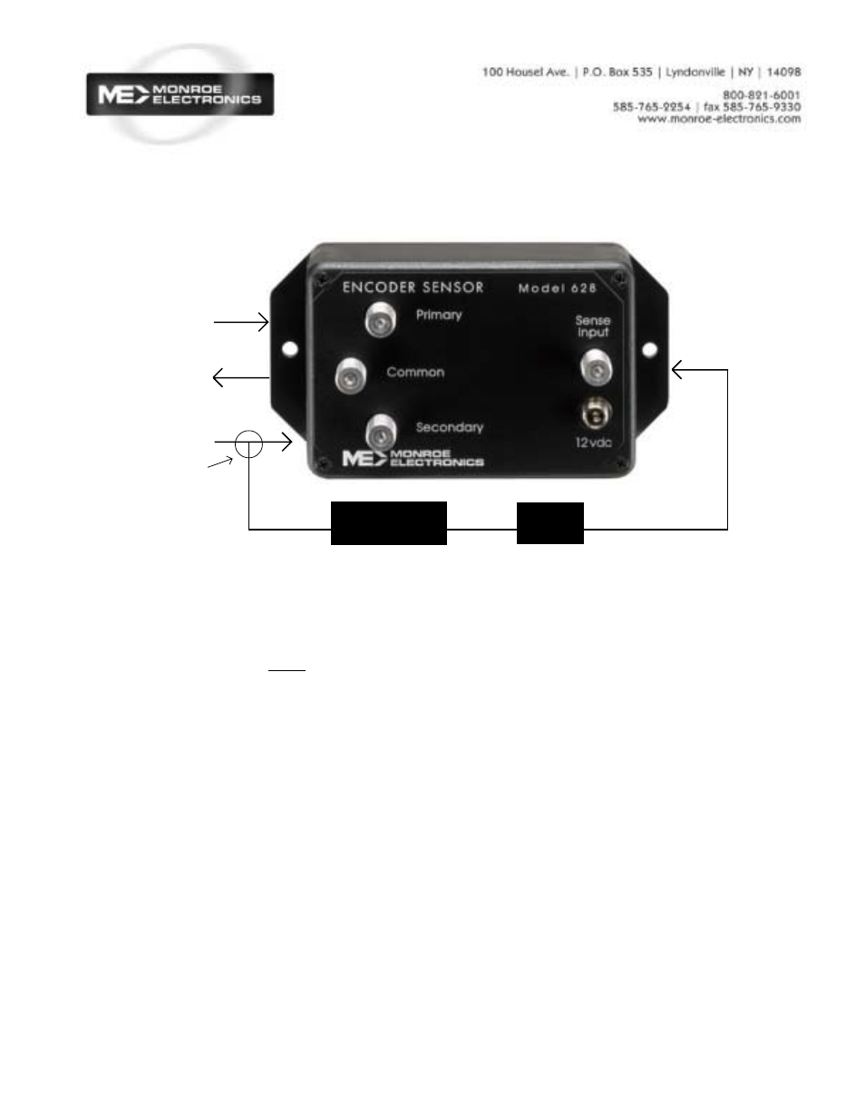
Installation
1.The Sense Input signal must
be a 1 Vp-p scrambled video sig-
nal. Connect the Encoder ’s
scrambled video output to the
628’s Sense Input.
2. Connect your barker channel
to the Primary Input. This is
normally an IF signal.
3. Connect your Encoder’s IF
ouput to the 628’s secondary
Input.
4. Connect the Common output
of the 628 to your modulator’s
input.
5. Plug the power supply
provided into the 12VDC input
on the unit
Specifications
RF Isolation
> 60 dB @ 450 Mhz
Sense Input Level
1 V p-p Video ± 10 %
Levels below approximately 0.8
V p~p should cause secondary
to connect to the output.
Power Requirement
100-240VAC
±
2%, 50/60 Hz.
Power pack output; +12 VDC
Physical
5.25” H X 2.75” W X 2” D
1 lb.
Operation
The 628’s sensing circuit moni-
tors the loss of scrambled video.
The absence of the scrambled
video causes the 628 to auto-
matically switch to the primary
input. It will remain in this state
until the scrambled video returns
to the sense input causing the
628 to switch back to the sec-
ondary input.
Normal IF In
IF Out
Scrambled IF In
Directional
Coupler
Scrambled
Video
IF In
Video Out
Demodulator
Attenuator
(Pad)