Monroe Electronics R175 User Manual
Model r-175 vertical interval switch
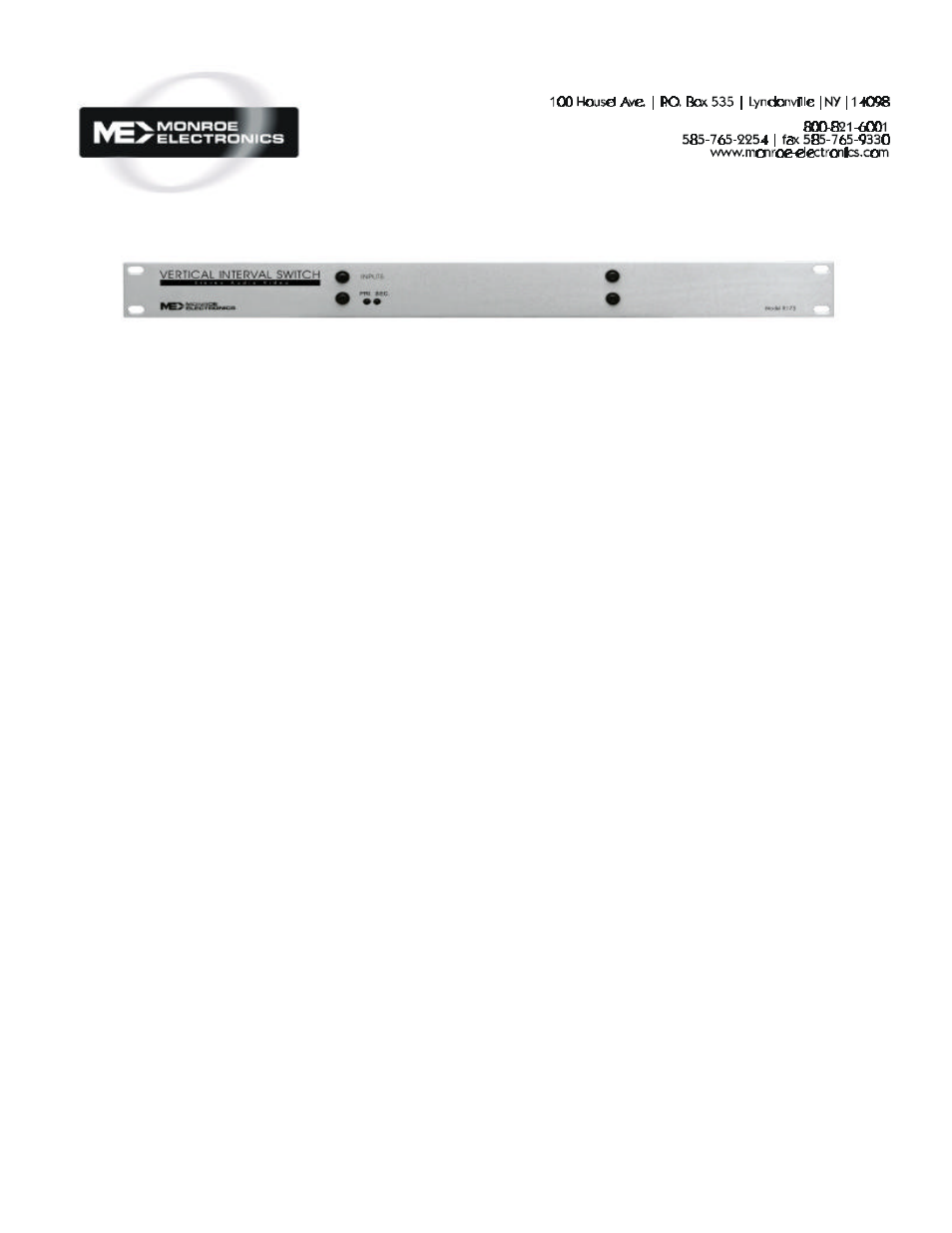
Model R-175 Vertical Interval Switch
Installation
Connect the COM outputs on
the R175 to your equipment’s
inputs.
Connect your primary
audio/video signal sources to
the PRI inputs on the R175.
Connect your secondary
audio/
video signal sources to the
SEC inputs on the R175.
Screw the wires from the
supplied
power pack to the two
connector power input on the
rear of the unit.
A TTL level control signal or
a debounced dry contact
across GND and SET on the
EXT CTRL connector will
change the output from the
primary to the secondary, if a
baseband video signal of at
least 0 dB is present at
primary input.
Relay Connection
Connect the normally open
(NO) contact to SET.
Connect the relay common
(COM) to GND.
Open Collector:
Connect your transistor’s
collector to SET and the
transistor’s emitter to GND.
Operation
The R175’s primary (PRI)
inputs are normally
connected to the common
(COM) outputs. It remains in
this state until the SET input
is connected to GND, and a
baseband video signal of at
least 0 dB is present at the
primary input. The unit will
switch during the vertical
blanking interval of the video
signal. This connects the
secondary (SEC) input to
common (COM) for the
duration of the connection.
The LEDs on the front panel,
when lit, indicate which input
is connected to the output.
Specifications
Video
75 ohms ; ‘BNC’ connectors
>80 dB isolation at 5 MHz
Video Return Loss
> 25dB
Audio
Balanced stereo; screw
terminals;
>90 dB isolation
Control Input
1 mA maximum to GND.
Power Requirement
117VAC ±10%, 60 Hz.
Power pack output; 12 VAC
Physical
1.75"H x 19"W x 4"D
Weight 2 lbs.
Design and specifications are subject to
change without notice.