Monroe Electronics R176 User Manual
Model r-176 vertical interval switch, Installation, Programming
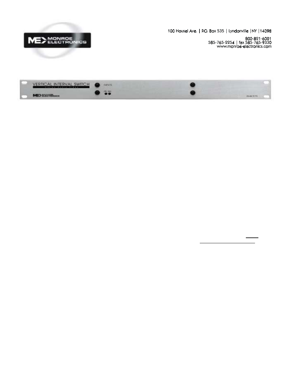
Model R-176 Vertical Interval Switch
Installation
Connect the COM outputs on the
R176 to the video and audio inputs
on your modulator.
Connect your primary audio/video
signal sources to the PRI Inputs on
the R176.
Connect your secondary audio/
video signal sources to the SEC
inputs on the R176.
Screw the wires from the supplied
power pack to the two connector
power input on the rear of the unit.
A TTL level control signal or a
dry contact across GND and Set
on the EXT CTRL connector will
change the output from the primary
to the secondary, if a baseband
video signal of at least 0 dB is
present.
The unit will also switch if the ON
command DTMF (Cue Tone) code
is input to the DTMF and GND
inputs, and the baseband signal is
present. It will switch back to the
primary on receiving the DTMF
(Cue Tone) OFF command.
Programming
To program the Cue Tone de-
coder, connect a Touch Tone
telephone to DTMF and GND
inputs. With the power off, remove
the cover from the unit. On the pc
board install the jumper across
JP101. Re-apply power.
Press and hold the # button on the
telephone until the relays pulse on
and off (click) once.
Press and hold down the * button
until the relays pulse on and off
(click) 3 times.
Enter the number of digits to be
used for the On/Off code. You
may use from 1 to 4 digits.
The unit will click once if the entry
is valid.
If the entry is not valid the unit will
click 5 times and exit programming
mode. Start over.
If the entry was valid, enter the On
Code. The unit will click three
times once the selected number of
digits has been entered.
Enter the digits for the Off Code.
The unit will click three times once
the selected number of digits has
been entered.
Please Note:
The On and Off codes must be
different. If programmed the same
the relay will always be turned on
when the code is entered.
Codes must be entered within 3
seconds, or the unit will click 5
times and exit programming mode.
If, at any time during
programming the relays click 5
times, an error has occurred.
Return to the start of the
programming procedure and
reprogram the unit.
Programming is complete.
Program Test
Test the system by entering the
cue tones for the ON command on
the telephone keypad. Verify that
the red light on the front panel
goes on. Next enter the cue tones
for the OFF command, and verify
the led turns off.
If the switches work correctly,
remove power from the unit. Next
remove the jumper from the two
pins on JP101, re-install it on only
1 pin. Replace the cover and re-
apply power. Disconnect the
telephone, and connect the audio
outputs from your source of cue
tones to the DTMF and GND
terminals.
**Remember, that the audio relays
work in the absence of audio or
video signals, but the video
switch WILL NOT WORK if there
is no input of video to the
primary (or normally closed) video
input.**
Relay Control Connection
Connect the normally open (NO)
contact to Set.
Connect the relay common (COM)
contact to GND.
Open Collector Control
Connect your transistor’s collector
to Set and the transistor’s emitter
to GND.