Appendix d: signal connection of di/do, Gpio pinout description sw1 setting – NEXCOM VTC 1010 User Manual
Page 80
Advertising
Copyright © 2013 NEXCOM International Co., Ltd. All Rights Reserved.
66
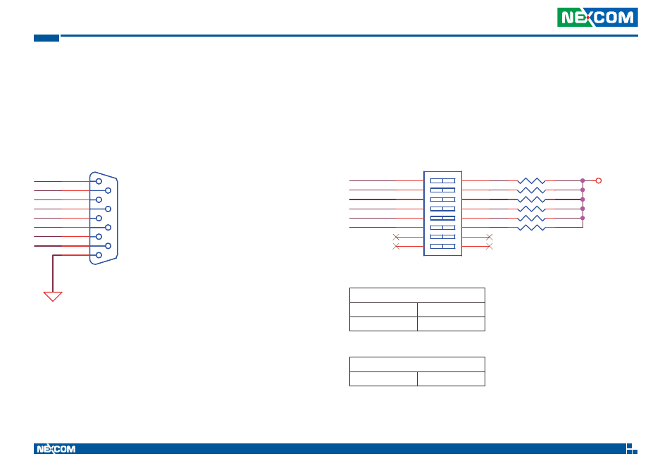
Appendix D: Signal Connection of DI/DO
VTC 1010 User Manual
Appendix D: Signal Connection of DI/DO
GPIO Pinout Description
SW1 Setting
GPIO1
GPIO3
CAN1_H
GPIO6
GPIO2
CAN1_L
GPIO5
GPIO4
ISO_GND
SIO-F-90-5.08mm
P4
SIO-F-90-5.08mm
5
9
4
8
3
7
2
6
1
GPIO1
GPIO2
GPIO3
GPIO4
GPIO5
GPIO6
VCC5
PO
DIP SW 2X8
PO
SW1
DIP SW 2X8
1
2
3
4
5
6
7
8
14
13
12
11
10
9
15
16
330Ω
GPIO (SW1)
On
Pull up VCC5
Off
Don’t Care
GPIO (SW1)
SW1.1~SW1.6
Pull up VCC5
Default Settings:
Note: By default, pin 1, 2 and 3 are configured for GPO, while pin 4, 5 and 6 are configured
for GPI.
Advertising