Round connection, Operational guides, Ft420ab – OT Systems FT420AB User Manual
Page 11: Eries, Ransmitter, 5) operational guides
FT420AB Series Installation & Operation Manual
11
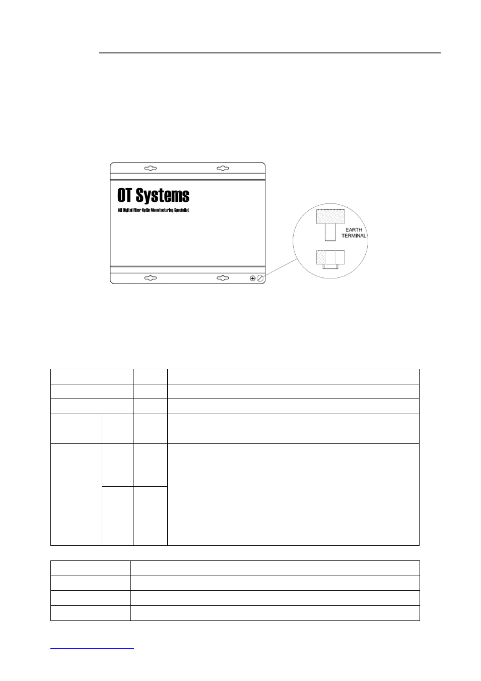
4.3 Ground connection
For enhanced safety to reduce the risks of electrical shock and physical damage, caused by
lightning and other power surges, as well as a connection to the surge suppresion devices in the
product, a screw terminal is provided on the Standalone cabinets (Fig. 4.5). It is highly
recommended that the Standalone unit have good ground connections to the buildings ground in
accordance with the local codes.
Fig. 4.5 Standalone unit earth ground terminal location
(5) Operational Guides
5.1 FT420AB Series Transmitter
LED Indicators
Indicator
Color
Description
PWR
Red
Lit when power is supplied to the Transmitter.
OL
Yellow
Lit when optical signal from receiver to transmitter is active.
VIDEO IN /
VIN
V1-V4
Green
Lit when video signals are fed into the VIDEO IN connectors.
AUDIO
LEVEL
IN
Red
a) Each audio channel has a single column of Four LEDs assigned
for displaying the input or output audio levels.
b) The LEDs (Input/Output) are lit in proportion to the signal
strength.
c) An increase/decrease of signal level of about 3dB will light up/turn
off an individual LED. All LEDs will go out at or less than -16dBm,
and all are lit when the level attains +6dBm or over.
OUT
Green
Signal Ports
OPT - ST (or FC) Optical Connector for fiber cable connection.
VIDEO IN - BNC Video Connectors for video signal inputs.
AUDIO 1 - 7-pin Screw Terminal Blocks for audio signal.
AUDIO 2 - 7-pin Screw Terminal Blocks for audio signal.